
Novel elevator structure

A new type of elevator technology, which is applied to elevators, lifts, transportation and packaging in buildings, etc., can solve the problems of the location limitation of the main engine, the decrease of elevator comfort, and the reduction of elevator comfort, so as to reduce the failure rate and eliminate Effects of pressure, energy efficiency improvement and elevator operation comfort

Inactive Publication Date: 2013-03-27
GIANT KONE ELEVATOR CO LTD
View PDF0 Cites 8 Cited by
  • Summary
  • Abstract
  • Description
  • Claims
  • Application Information

AI Technical Summary

Problems solved by technology

On the one hand, this friction force greatly reduces the energy efficiency of the elevator. On the other hand, the change of the friction force due to the change of the friction coefficient of the guide rail causes a decrease in the comfort of the elevator.
When the elevator is at rest, because the pressure always acts locally on the guide rail through the guide shoe (rolling guide shoes are generally used to reduce the friction coefficient because of the high pressure), which causes local deformation of the guide shoe. use, when returning from work during the day), the local deformation of the guide shoe has accumulated to a large extent. When the guide shoe rolls for the first time, there will be an obvious vibration in each cycle of the guide shoe, which greatly reduces the comfort of the elevator. The deformation increases with the number of uses It will gradually decrease, and the vibration will also tend to be less obvious. If the elevator is used less frequently, such as a home elevator, the deformation is difficult to recover by frequent use. In most cases, the vibration is always obvious
[0004] Since the suspension point is on the side of the car, in order to make the suspension center as parallel as possible to the line connecting the car center of gravity and the car wall to improve comfort, reduce failure rate and operating cost, the arrangement position of the main engine is relatively limited, so the size of the main engine is also limited restricted

Method used


Image

  • Novel elevator structure
  • Novel elevator structure
  • Novel elevator structure

Examples


Embodiment 1

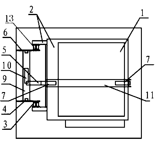
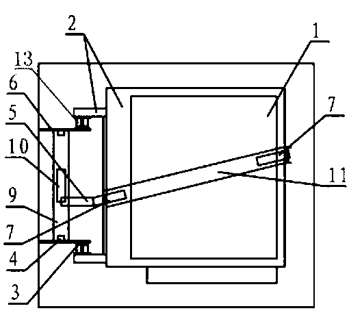
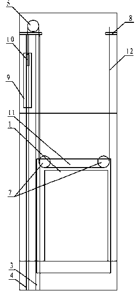
[0027] as attached figure 1 with 3 As shown, a new type of elevator structure includes a car 1 and a car traction load-bearing system. The car traction load-bearing system includes a car frame 2, a guide rail frame 6, a traction machine and a wire rope 12; the traction machine is provided with a traction The guide pulley 5; the car frame 2 is provided with a car wheel 7; the guide rail frame 6 is provided with a car guide rail 3, a counterweight guide rail 4 and a counterweight frame 9; the counterweight frame 9 is provided with a counterweight wheel 10; the car frame 2 is connected with the car guide rail 3 through the guide shoe 13, and it also includes a rope head plate 8; the rope head plate 8 and the traction sheave 5 are respectively located on both sides of the car 1; there are two car wheels 7; There is a base 11 for installing two car wheels 7; one end of a steel wire rope 12 is fixed on the rope head plate 8, and the steel wire rope 12 passes around the two car whee...

Embodiment 2

[0029] as attached figure 1 with 4 As shown, the difference from the first embodiment is that the base 11 is located at the bottom of the car 1 .

Embodiment 3

[0031] as attached figure 2 with 3 As shown, the difference from the first embodiment is that the length direction of the base 11 is not perpendicular to the side of the car 1 where the two ends of the base 11 are located.


PUM


Abstract

The invention belongs to the field of elevators and particularly relates to a novel elevator structure. The novel elevator structure comprises a lift car and a lift car traction bearing system, wherein the lift car traction bearing system comprises a lift frame, a guide rail frame, a traction machine and a steel wire rope, a traction wheel is arranged on the traction machine, lift car wheels are arranged on the lift frame, a lift car guide rail, a counter-weight guide rail and a counter-weight frame are arranged on the guide rail frame, the novel elevator structure also comprises a rope head plate, the rope head plate and the traction wheels are respectively positioned at two sides of the lift car, the number of the lift car wheels is two, a base used for installing the lift car wheels is arranged on the lift frame, one end of the steel wire rope is fixedly arranged on the rope head plate, and the steel wire rope sequentially bypasses the two lift car wheels, the traction wheel and the counter-weight wheel from the rope head plate. Through the structure, the energy efficiency of a host machine and the operation comfort feeling of the elevator are also greatly improved, and the failure rate of the elevator is reduced. The structure adopts the two lift car wheels, the arrangement is freer, and the arrangement flexibility of the traction machine can also be greatly improved through the inclined arrangement of the two lift car wheels.

Description

technical field [0001] The invention belongs to the field of elevators, in particular to a novel elevator structure. Background technique [0002] In order to improve the utilization rate of the shaft, the elevator needs to install all the guide rails on one side in some cases such as beautiful or special shaft structure, such as the backpack frame structure of some home elevators. It is necessary to invent a reasonable arrangement method to improve the comfort and energy efficiency of the elevator and reduce the failure rate. [0003] When the elevator car frame adopts a backpack frame structure, due to the large deviation between the suspension center and the center of gravity of the car, the car has a great pressure on the guide rail level through the guide shoes. During the operation of the elevator, because of this pressure, a large friction force will be generated between the guide shoe and the guide rail, especially in a small load elevator, this friction force will ...

Claims


Application Information

Patent Timeline
IPC IPC(8): B66B9/00B66B7/06B66B7/00
Inventor 李雪荣郑庆辉董张强
Owner GIANT KONE ELEVATOR CO LTD
Learn More