Feeding system for powdery polyolefin catalyst

A polyolefin catalyst and feeding system technology, applied in feeding devices, chemical instruments and methods, chemical/physical processes, etc., can solve the problems of instability, blocking feeding, deposition, etc., and achieve the effect of smooth pipeline and stable control

Active Publication Date: 2013-03-27
CHINA PETROLEUM & CHEM CORP +1
View PDF6 Cites 20 Cited by
  • Summary
  • Abstract
  • Description
  • Claims
  • Application Information

AI Technical Summary

Problems solved by technology

[0008] The technical problem to be solved by the present invention is to provide a powdery polyolefin catalyst feeding system, which can solve the problem of easy deposition in the system during the feeding process of the powder catalyst in the prior art without increasing the equipment cost. Blockage and other problems that cause unstable feeding

Method used


Image

  • Feeding system for powdery polyolefin catalyst
  • Feeding system for powdery polyolefin catalyst

Examples


Embodiment 1

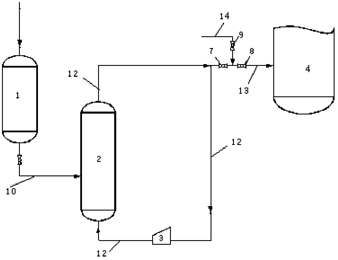
[0029] Such as figure 1 , The catalyst tank is a 2-liter sealed steel pressure vessel containing 200 grams of powdered catalyst. The intermediate tank is a 20-liter sealed steel pressure vessel, and the flow rate of the fan is 150 liters / hour.

[0030] Turn on the fan, the fan and the intermediate tank form a circulation loop, and the gas flows in the circulation loop; then the catalyst particles are intermittently added to the intermediate tank from the bottom of the catalyst tank, and flow together with the gas in the circuit between the fan and the intermediate tank. When the catalyst is fed, the automatic valve 7 is opened, the quantitative tube between the automatic valve 7 and the automatic valve 8 is filled with catalyst and gas, then the automatic valve 7 is closed, the automatic valve 8 and the automatic valve 9 are opened, and the high-pressure gas purge pipeline is connected 14, where the high-pressure gas used is N with a pressure of 1.8MPa 2 (Polymerization reac...

Embodiment 2

[0033] Such as figure 1 , The catalyst tank is a 2-liter sealed steel pressure vessel containing 200 grams of powdered catalyst. The tundish is a 20-liter sealed steel pressure vessel with a gas distributor placed in the lower part. The opening ratio of the gas distributor is 15%. The fan flow rate is 300 l / h.

[0034] Turn on the fan, the fan and the intermediate tank form a circulation loop, and the gas flows in the circulation loop; then the catalyst particles are intermittently added to the intermediate tank from the bottom of the catalyst tank, and flow together with the gas in the circuit between the fan and the intermediate tank. When the catalyst is fed, the automatic valve 7 is opened, the quantitative tube between the automatic valve 7 and the automatic valve 8 is filled with catalyst and gas, then the automatic valve 7 is closed, the automatic valve 8 and the automatic valve 9 are opened, and the high-pressure gas purge pipeline is connected 14, wherein the high-p...

Embodiment 3

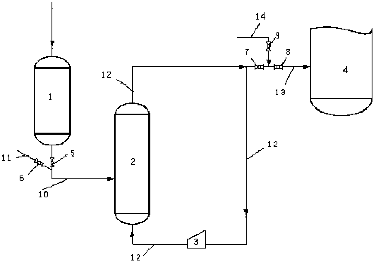
[0037] Such as figure 2 , The catalyst tank is a 2-liter sealed steel pressure vessel containing 200 grams of powdered catalyst. The intermediate tank is a 20-liter sealed steel pressure vessel, and the flow rate of the fan is 20 liters / hour.

[0038] Turn on the fan, the fan and the tundish form a loop, and the gas flows in the loop; when feeding the tundish 2, open the automatic valve 5, add catalyst particles to the tundish 2, close the automatic valve 5, then open the automatic valve 6, and connect Into the gas purge line 11, wherein the gas used is a pressure of N 2 , the pressure is 0.2 ~ 0.3MPa, the pressure of the tundish is generally normal pressure, the catalyst particles in the pipeline are completely blown into the circulation circuit of the tundish 2, and then the automatic valve 6 is closed; the catalyst particles are blown together with the gas in the fan and the tundish Flow in the circuit between, when feeding to the rear system 4, the automatic valve 7 is ...


PUM

PropertyMeasurementUnit
porosityaaaaaaaaaa

Abstract

The invention provides a feeding system for powdery polyolefin catalyst, and belongs to the field of olefin polymerization reaction. The system comprises a catalyst storage tank (1), an intermediate tank (2) and a fan (3), wherein the catalyst storage tank (1) is connected with the intermediate tank (2) by a pipeline (10); an automatic valve (5) is arranged on the pipeline (10); the fan (3) and the intermediate tank (2) form a circulating loop via a pipeline (12); the part, which is close to the top part of the intermediate tank, on the pipeline (12) is provided with an outlet which is connected with a back system (4) by a pipeline (13); an automatic valve (7) and an automatic valve (8) connected with each other in series are arranged on the pipeline (13); a quantitative tube is arranged between the automatic valve (7) and the automatic valve (8); and gas blowing pipelines are respectively arranged at the outlets of the automatic valve (7) and the automatic valve (8). The feeding system provided by the invention has the advantages that solid catalysts are stably and precisely controlled to be added in a reaction system under normal pressure and low cost.

Description

technical field [0001] The invention relates to an olefin polymerization reaction system, in particular to a powdery polyolefin catalyst feeding system. Background technique [0002] At present, most of the catalysts used in olefin polymerization in industry are solid particle type, and the feeding of this solid particle type catalyst is usually added by a specially designed catalyst feeding device, such as the solid catalyst feeding device adopted on the Unipol polyethylene device; there is also a After a complex preparation process, the catalyst is prepared into a certain concentration of slurry or paste, and then sent into the reactor with a metering system. In the above two methods, the equipment investment of the former is very high, the adding process is easy to block, and there is no accurate and effective method to know the catalyst content in the catalyst feeder. The preparation process of the latter is extremely complicated, and the preparation of a single catalys...

Claims


Application Information

Patent Timeline
Patent Type & Authority Applications(China)
IPC IPC(8): C08F10/00C08F2/01B01J4/00
Inventor 沈贻芳单薇马英孙剑凯张建新王建斌
Owner CHINA PETROLEUM & CHEM CORP
Why Eureka
Try Eureka