Yarn breakage detection method and yarn breakage detection device using method

A detection device and detection method technology, applied in textiles and papermaking and other directions, can solve the problems of high cost, difficult maintenance, increased uncertainty, etc., and achieve the effects of low installation position accuracy requirements, less interference, and easy implementation.

Active Publication Date: 2013-03-27
TIANJIN POLYTECHNIC UNIV
View PDF17 Cites 27 Cited by
  • Summary
  • Abstract
  • Description
  • Claims
  • Application Information

AI Technical Summary

Problems solved by technology

[0003] The utility model patent "yarn breakage detection device" (application number 02265359.7) installs the thermal sensor on the yarn guide hook or steel ring, and detects the friction between the yarn and the yarn guide hook and the steel ring and traveler through the thermal sensor The frictional heat is generated to detect whether the broken end occurs. This method requires the installation of sensors for each spindle, which requires a large investment.
The utility model patent "Yarn Breakage Detection Device" (application number 200520080973.7) discloses a yarn breakage detection device. Photoelectric sensors are installed at both ends of the roller seat, and the rays emitted by the photoelectric sensors pass through the lower edge of the front top roller. When the yarn breaks, the photoelectric sensor is used to detect the phenomenon of flying flowers and winding cot rollers, and the signal feedback device connected to the photoelectric sensor is used to issue a broken end indication. This method is susceptible to the influence of flying flowers in the environment, and there is a possibility of missing detection. , and it is impossible to determine the specific spindle position where the end break occurs
The utility model patent "Spinning Yarn Guide with Yarn Breakage Detection Device" (Application No. 200520045862.2) uses a specially designed yarn guide hook to detect yarn breakage, and a photoelectric sensor is installed on each yarn guide hook. The signal is sent to the controller. This method also needs to install a detection element for each spindle position, and the cost is relatively high.
The utility model patent "A device for automatic detection of yarn breakage and automatic jointing" (application number 201220009611.9) adds a guide rail and a moving trolley beside the steel ring plate. The moving trolley reciprocates on the guide rail, and uses an inductance probe to detect the steel wire during the reciprocating movement. The moving speed of the ring can be used to detect broken ends of the spun yarn. Using the inductance probe to detect the moving speed of the traveler has high requirements for the accuracy of the sensor and the accuracy of its installation position, especially when the traveler is small, which increases the uncertainty of detection.
Invention patent "Detection method for yarn twisting end breakage on spinning frame" (application number 201210009964.3) utilizes a photoelectric sensor or pressure sensor installed on the ring plate to detect the signal generated by the movement of the traveler to detect end breakage. The sensor is installed on the spindle position, and the cost is relatively high
These patents also have the problems of high implementation cost, large quantity, and difficult maintenance

Method used


Image

  • Yarn breakage detection method and yarn breakage detection device using method
  • Yarn breakage detection method and yarn breakage detection device using method
  • Yarn breakage detection method and yarn breakage detection device using method

Examples


Embodiment Construction

[0016] Further describe the present invention below in conjunction with embodiment and accompanying drawing thereof:

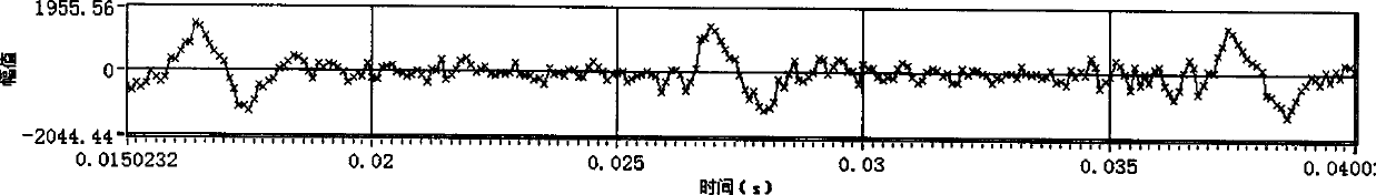
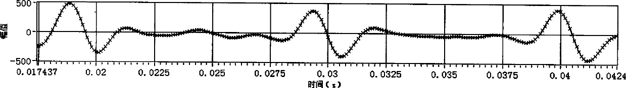
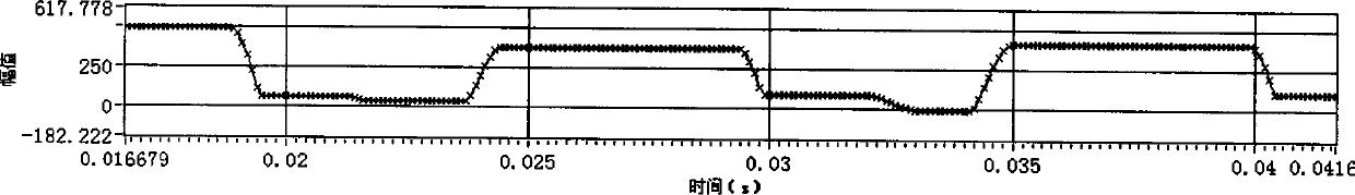
[0017] The yarn breakage detection method of the present invention uses a sound sensor to convert the measured sound into an analog audio signal, digitally samples the audio signal to obtain a digital sound signal, and judges whether the spun yarn breakage occurs according to the characteristics of the digital sound signal obtained by sampling.

[0018] The principle of the spun yarn breakage detection method of the present invention: the traveler and the steel ring have relative motion during spinning, which will generate friction sound. During normal spinning, if the influence of twist shrinkage is ignored, the speed of the traveler is equal to the speed of the spindle minus the front roller The delivery speed is divided by the circumference of the spun yarn. Therefore, the rotation speed of the traveler on the steel ring is slightly lower than the spindle sp...


PUM


Abstract

The invention discloses a yarn breakage detection method applied to a ring throstle and a yarn breakage detection device using the method. The yarn breakage detection method is characterized in that a microcontroller controls a voice sensor to acquire a voice signal at the outer side of a steel collar during spinning; if the detected voice signal always has pretty high wave peaks at every moment when a bead ring approaches to the voice sensor relative to the moment when the bead ring is pretty far away from the voice senor and the wave peak occurrence frequency is slightly lower than a spindle rotation frequency, the yarn at the spinner position has no breakage, otherwise, the yarn at the spinner position has breakage; preferably, the voice sensor is at the position on the same horizontal plane as or slightly higher than the steel collar in a vertical height direction; and the minimal distance in the level direction from the voice sensor to the axis in the vertical direction of the steel collar is greater than the maximal outer diameter of a movement locus of the bead ring and a movement locus of a yarn ballooning. The yarn breakage detection device disclosed by the invention is designed according to the yarn breakage detection method disclosed by the invention.

Description

technical field [0001] The invention relates to the field of spun yarn breakage detection in the spun yarn spinning process, in particular to a spun yarn breakage detection method and a spun yarn breakage detection device using the method, and the method and the device are used in ring spinning frames. The spun yarn breakage detection method can detect the spun yarn breakage that occurs during the spinning process of the ring spinning frame; the spun yarn breakage detection device using this method is installed on the ring spinning frame and runs along the length of the ring plate of the spinning frame Direction movement, during the movement, it detects the broken end of the spun yarn during the spinning process and presents the specific spindle position information of the broken end to the spun yarn operator. Background technique [0002] Among the various spinning processes, the spinning process requires the most labor. The main responsibility of the spinning machine opera...

Claims


Application Information

Patent Timeline
Patent Type & Authority Applications(China)
IPC IPC(8): D01H13/32D01H13/16
Inventor 吕汉明马崇启傅宏俊吴晓青
Owner TIANJIN POLYTECHNIC UNIV
Why Eureka
Try Eureka