Eureka AIR delivers breakthrough ideas for toughest innovation challenges, trusted by R&D personnel around the world.

Multi-stage hydraulic expansion tail pipe suspension system with reducing expansion cone for horizontal well for thermal recovery of heavy oil

A heavy oil thermal recovery and liner suspension technology, which is applied in earth-moving drilling, wellbore/well components, etc., can solve the problems of scrapped wellbore, damage to the inner wall of the expansion pipe, intensified formation instability, etc., to solve the problem of steam channeling The effect of burying with sand, reducing the friction of running in, and keeping the wellbore clean

Active Publication Date: 2013-03-27
SOUTHWEST PETROLEUM UNIV
View PDF8 Cites 15 Cited by
  • Summary
  • Abstract
  • Description
  • Claims
  • Application Information

AI Technical Summary

Problems solved by technology

However, due to the special wellbore environment of heavy oil thermal recovery horizontal wells, there are the following difficulties in the application of existing expansion liner hanging tools: (1) Practice has proved that hydraulic expansion is more operable than mechanical expansion, but the existing expansion liner Most of the hanging tools use direct pressure expansion or single-stage hydraulic cylinder expansion, which requires high pump pressure and high construction risks. Once pressure leaks, it will not be able to continue to expand; (2) When performing expansion operations, especially in highly deviated wells When performing expansion operations in sections or curved well sections, there is a high risk of the blockage of the conventional solid expansion cone. If the expansion cone is forced to be lifted up after encountering blockage during expansion from top to bottom, the inner wall of the expansion tube will be damaged and the service life of the tool will be affected; However, when the upper expansion is blocked, it is difficult to lift the expansion cone, which will bring a huge workover workload, and even cause the wellbore to be scrapped. The use of variable-diameter expansion tools can effectively solve this problem, but currently there are The expansion liner suspension system of the variable diameter expansion tool has not been reported yet; (3) The expansion liner suspension tool after setting is faced with a high-temperature steam environment of 300 °C, and the ambient temperature can reach 600 °C or even higher during fire flooding development. High, such a high temperature can easily lead to the failure of the seal on the hanging tool, and the channeling of high-temperature steam through the gap of the seal will affect the steam injection effect of the oil well; at the same time, the high temperature will change the stress state of the rock and make the formation unstable. During oil production, the formation fluid carries a large amount of sand into the wellbore through the gap of the seal, blocking or even burying the extraction equipment in the well, seriously affecting the normal production of the oil well
[0003] Chinese patent 2012200061410 discloses an expansion tube hanging hanger, which only has a hydraulic expansion system. When the hydraulic cylinder fails, the tool cannot continue to be used; the expansion cone is a fixed structure, and it is not easy to solve after the expansion encounters resistance; The upper end of the expansion tube is provided with three rubber rings, which can easily lead to failure of the seal in a high temperature environment and poor stability in use

Method used


Image

  • Multi-stage hydraulic expansion tail pipe suspension system with reducing expansion cone for horizontal well for thermal recovery of heavy oil
  • Multi-stage hydraulic expansion tail pipe suspension system with reducing expansion cone for horizontal well for thermal recovery of heavy oil
  • Multi-stage hydraulic expansion tail pipe suspension system with reducing expansion cone for horizontal well for thermal recovery of heavy oil

Examples


Embodiment Construction

[0022] The present invention will be further described below in conjunction with accompanying drawing, protection scope of the present invention is not limited to the following:

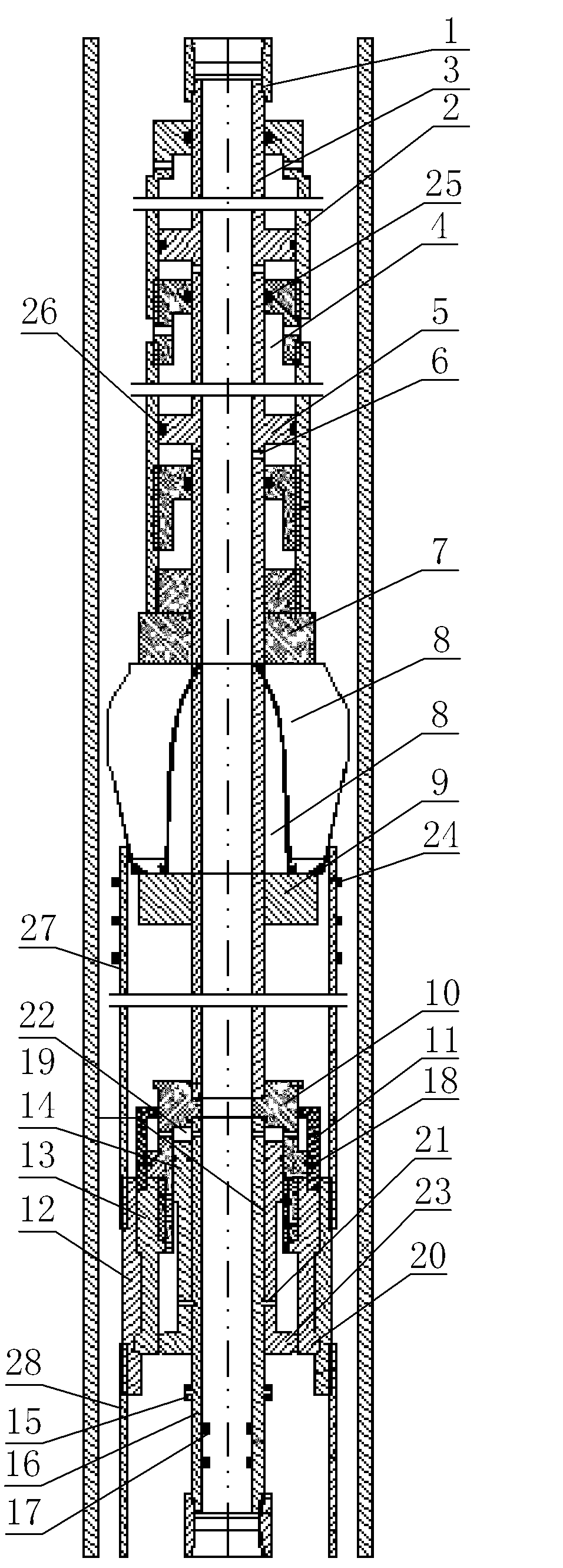
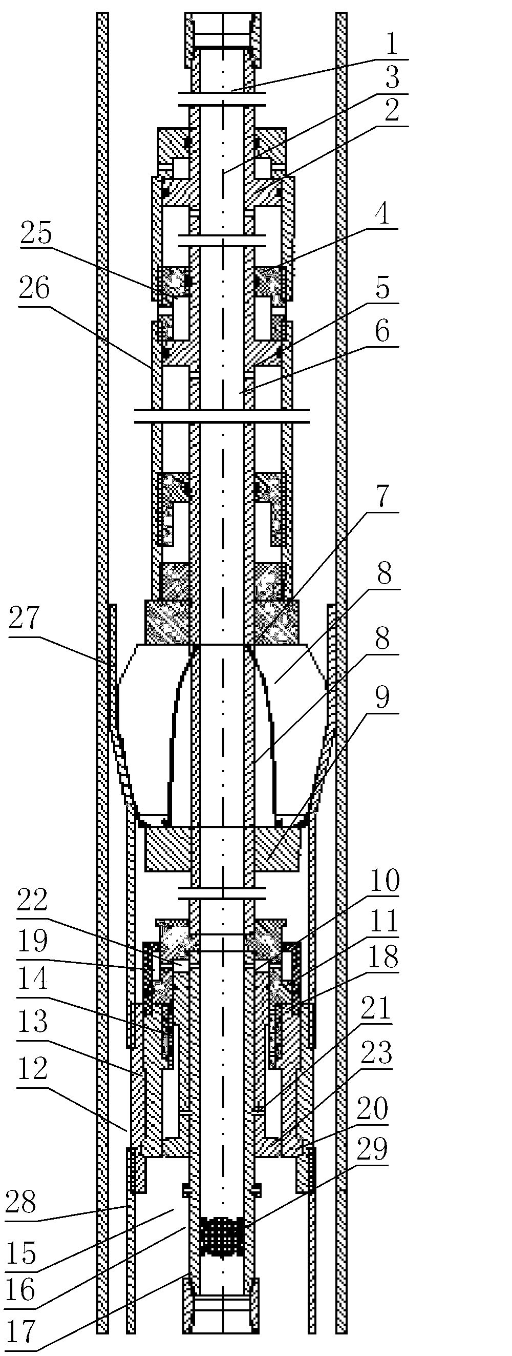
[0023] Such as figure 1 As shown, the multi-stage hydraulic expansion liner suspension system for heavy oil thermal recovery horizontal wells with variable-diameter expansion cones includes an upper joint 1, a multi-stage hydraulic cylinder power system, variable-diameter expansion cones, expansion tube hangers 27 and hydraulic- Mechanical double-acting hands-off system, the upper joint 1 is provided with an internal thread.

[0024] The multi-stage hydraulic expansion liner suspension system includes a multi-stage hydraulic cylinder liner 2 and a hollow piston rod 3, the inner thread at the lower end of the upper joint 1 is connected with the upper end of the hollow piston rod 3, and the multi-stage hydraulic cylinder liner 2 is provided with a A plurality of mutually independent hydraulic cylinder...


PUM


Abstract

The invention discloses a multi-stage hydraulic expansion tail pipe suspension system with a reducing expansion cone for a horizontal well for thermal recovery of heavy oil. The multi-stage hydraulic expansion tail pipe suspension system comprises a multi-stage hydraulic cylinder power system, the reducing expansion cone, an expansion pipe hanger (27) and a hydraulic-mechanical dual-acting release system and also comprises a multi-stage hydraulic cylinder sleeve (2) and a hollow piston rod (3), the reducing expansion cone comprises an upper claw plate (7), a reducing expansion block (8) and a lower claw plate (9), and the hydraulic-mechanical dual-acting release system comprises a release body (10), a torque sliding sleeve (11), a release coupling (12), a sleeve claw (13), a pin clamping seat (14) and a pressure-keeping ball seat (16). The multi-stage hydraulic expansion tail pipe suspension system has the beneficial effects that since the multi-stage hydraulic cylinder power system is adopted, the safety factor is larger, and the scope of application is wider; since the reducing expansion cone is adopted, the adaptability of the system is improved; and since the hydraulic-mechanical dual-acting release system is adopted, operating risks are reduced, and the stability of the device is improved.

Description

technical field [0001] The invention relates to the technical field of oil well completion, in particular to a multi-stage hydraulic expansion liner suspension system for heavy oil thermal recovery horizontal wells with variable-diameter expansion cones. Background technique [0002] Horizontal well technology is widely used in the thermal recovery of heavy oil due to its advantages of wide thermal sweep range, high degree of reservoir production and good comprehensive development benefits. The liner hanging completion technology is the key link to give full play to the productivity advantages of thermal recovery horizontal wells. The use of liner hanging completion technology in thermal recovery horizontal wells can provide a larger wellbore size for later steam injection and oil production operations, and can also reduce casing Pipe overlapping saves cement consumption and reduces drilling costs. As far as a single well is concerned, the casing cost saved can reach hundred...

Claims


Application Information

Patent Timeline
Patent Type & Authority Applications(China)
IPC IPC(8): E21B23/04
Inventor 李黔尹虎刘辉吴昊杨先伦
Owner SOUTHWEST PETROLEUM UNIV
Why Eureka
Eureka Blog
Learn More