
Embracing hoop applied to auxiliary pole mounting of transformer and transformer rack assembling method

A technology of transformers and auxiliary poles, which is applied in the installation/support/suspension of transformers/reactors, substations mounted on columns, detachable fasteners for friction clamping, etc. Large gap, unsightly and other problems, to achieve the effect of convenient installation and fixation, convenient installation and simple structure

Active Publication Date: 2013-03-27
SHANGHAI INTELLIGENCE POWER ENG CO LTD
View PDF8 Cites 7 Cited by
  • Summary
  • Abstract
  • Description
  • Claims
  • Application Information

AI Technical Summary

Problems solved by technology

[0005] 2. The diameter difference between the two poles is large, and the trapezoidal deformation is large, which exceeds the adjustment range of the track position at the bottom of the transformer
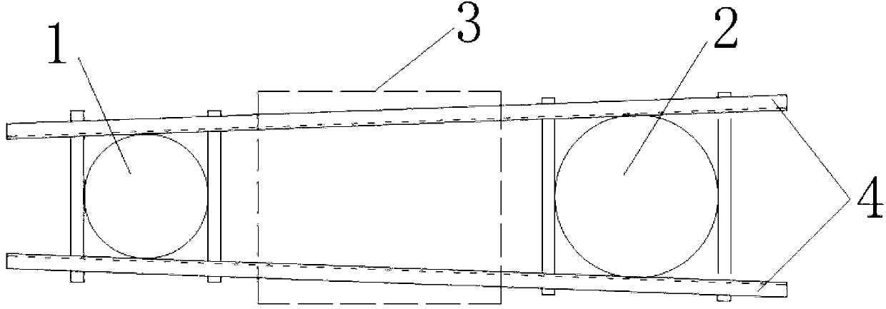
[0006] 3. If there is a big gap between the diameters of the two poles, and the trapezoid becomes larger, the installation of the transformer will be difficult, easy to slide, poor in stability, and unsightly. The most important thing is that it will not meet the design requirements for transformer installation, and will not pass the inspection. Measures such as adjusting and adding shims and existing hoops to install the transformer

Method used


Image

  • Embracing hoop applied to auxiliary pole mounting of transformer and transformer rack assembling method
  • Embracing hoop applied to auxiliary pole mounting of transformer and transformer rack assembling method
  • Embracing hoop applied to auxiliary pole mounting of transformer and transformer rack assembling method

Examples


Embodiment Construction

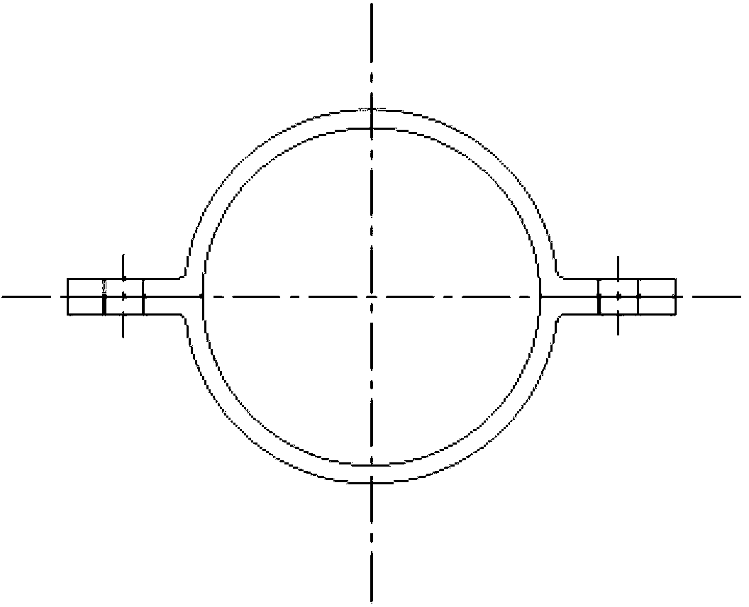
[0024] Such as Figure 4 As shown, in this embodiment, a hoop for installing the sub-pole of a transformer includes two hoop plates 5 with the same structure and a semi-circular arc belt shape. A bolt connection (not shown in the figure) used as a detachable locking mechanism for locking the two hoop plates 5 in the engaged state, wherein the two ends of the hoop plates 5 extend outward symmetrically and are arranged on the same plane The long lugs 6 used to increase the diameter of the secondary rod, and a channel steel 7 used as a spacer are respectively arranged between the long lugs 6 of the two hoop plates 5, and the bolt connection is passed through the long lugs 6 and the channel steel 7 The mounting holes (not marked in the figure) lock the two hoop plates 5 in the engaged state.

[0025] Such as Figure 5 As shown, this embodiment also proposes a method for assembling a transformer stand using the above-mentioned hoop when the diameter difference between the seconda...


PUM


Abstract

The invention discloses a transformer rack assembling method which employs an embracing hoop. The method comprises the following steps: 1, embracing and sleeving two hoop plates on an auxiliary pole, clamping U-bars with corresponding thickness between long ears of the two hoop plates; 2, placing the long ears on the both outsides of the auxiliary pole, then locking the two hoop plates by a bolt connection piece connected and fixed on the two hoop plates, the connecting piece being used for detaching locking mechanism, 3, arranging two mounting clamp plates which are used for bearing the transformer at the two sides of the auxiliary pole and a main pole, and arranging the two mounting clamp plates on the two long ears of the hoop plates in a clamping manner. The embracing hoop applied to the auxiliary pole mounting of the transformer and the transformer rack assembling method have the advantages that the structure is simple, the difficulty of mounting is reduced, the effective mounting can be carried out in a manner that the situation that the circular diameter gap of the two poles is large is overcome, and the requirements on the mounting and designing are better met.

Description

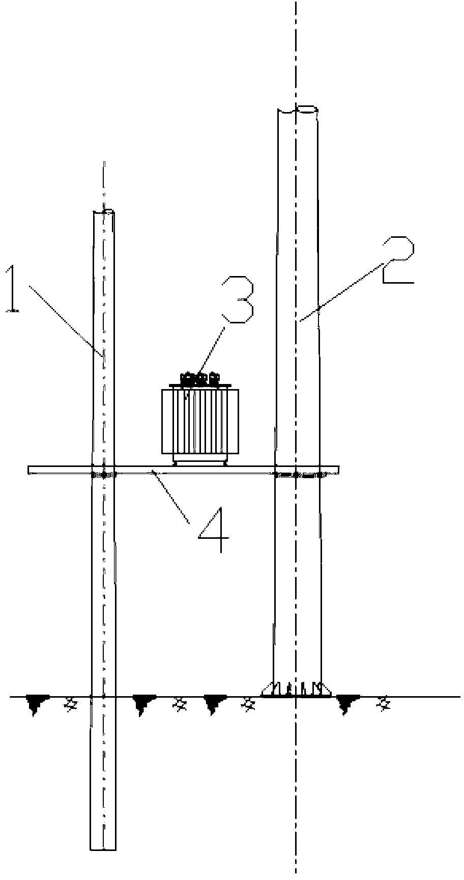
technical field [0001] The invention relates to the technical field of transformer stand installation parts and installation methods, in particular to a hoop used for installing a secondary pole of a transformer and a transformer stand assembly method. Background technique [0002] At present, whether it is a partial prestressed pole or a flanged pole, the overhead line pole of the distribution network generally adopts a tapered pole, which has the characteristics of durability, high stability and lightning protection. But also produced a problem at the same time, for the same tapered electric pole, its installation position is different, and electric pole radius is also different; Make to run into certain trouble to the actual installation operation of distribution transformer on overhead line. [0003] Under the premise of meeting the design requirements of transformer installation, install the transformer. Such as figure 1 and figure 2 As shown, the installation of th...

Claims


Application Information

Patent Timeline
Patent Type & Authority Applications(China)
IPC IPC(8): F16B2/02H01F27/06H02B5/02
Inventor 俞谊
Owner SHANGHAI INTELLIGENCE POWER ENG CO LTD
Learn More