
Mechanical vibration signal vibration-damping and filtering device for high-speed gear box

A mechanical vibration, high-speed gear technology, applied in mechanical equipment, vibration suppression adjustment, spring/shock absorber, etc., can solve the problems of insignificant vibration damping effect, influence experimental effect, and lack of independence, and achieve compensation for axial Displacement, flexibility and independence

Inactive Publication Date: 2014-07-02
XI AN JIAOTONG UNIV
View PDF4 Cites 0 Cited by
  • Summary
  • Abstract
  • Description
  • Claims
  • Application Information

AI Technical Summary

Problems solved by technology

[0002] The vibration problem of high-speed rotating machinery has always been a hot spot of concern, especially the signal output from the high-speed gearbox contains a variety of harmonic vibration signals, which interfere and affect the experimental results
The commonly used vibration reduction method is to use a shock absorber to separate the possible vibration from the frame, such as rubber shock absorber, damping spring shock absorber, etc. Although this type of shock absorber has a simple structure and low price, it is not independent. Strong, lacks flexibility, needs to be installed on the test piece or on the test piece base, may change the structure of the test piece, and the vibration reduction can only be performed after the system transmits the vibration signal to the test piece, and cannot be used when the vibration signal enters the test filter out before parts, the vibration reduction effect is not obvious

Method used


Image

  • Mechanical vibration signal vibration-damping and filtering device for high-speed gear box
  • Mechanical vibration signal vibration-damping and filtering device for high-speed gear box
  • Mechanical vibration signal vibration-damping and filtering device for high-speed gear box

Examples


Embodiment Construction

[0025] The present invention will be further described in detail below in conjunction with the accompanying drawings.

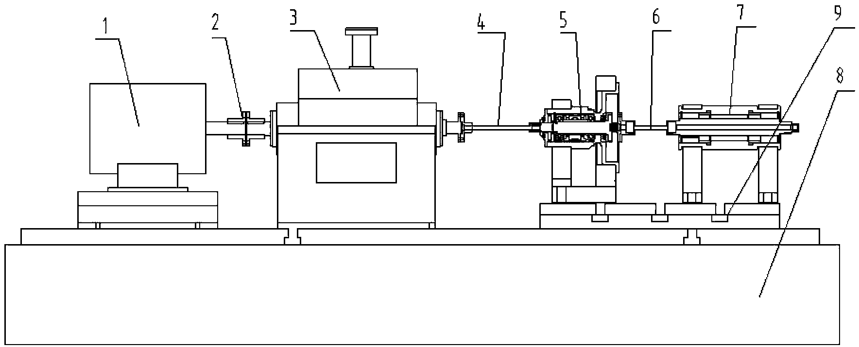
[0026] see figure 1 , a mechanical vibration signal damping and filtering device for a high-speed gearbox, including a motor 1, the output shaft of the motor 1 is connected to the input of a gearbox 3 through a diaphragm coupling 2, and the output of the gearbox 3 is connected through a spline coupling One end of the transition rotor 4 is connected to the transition rotor part 5, and the other end of the transition rotor part 5 is connected to the test piece 7 through the thin-walled sleeve coupling 6, and the test piece 7 is installed on the overall test bench 8 through the installation platform 9.

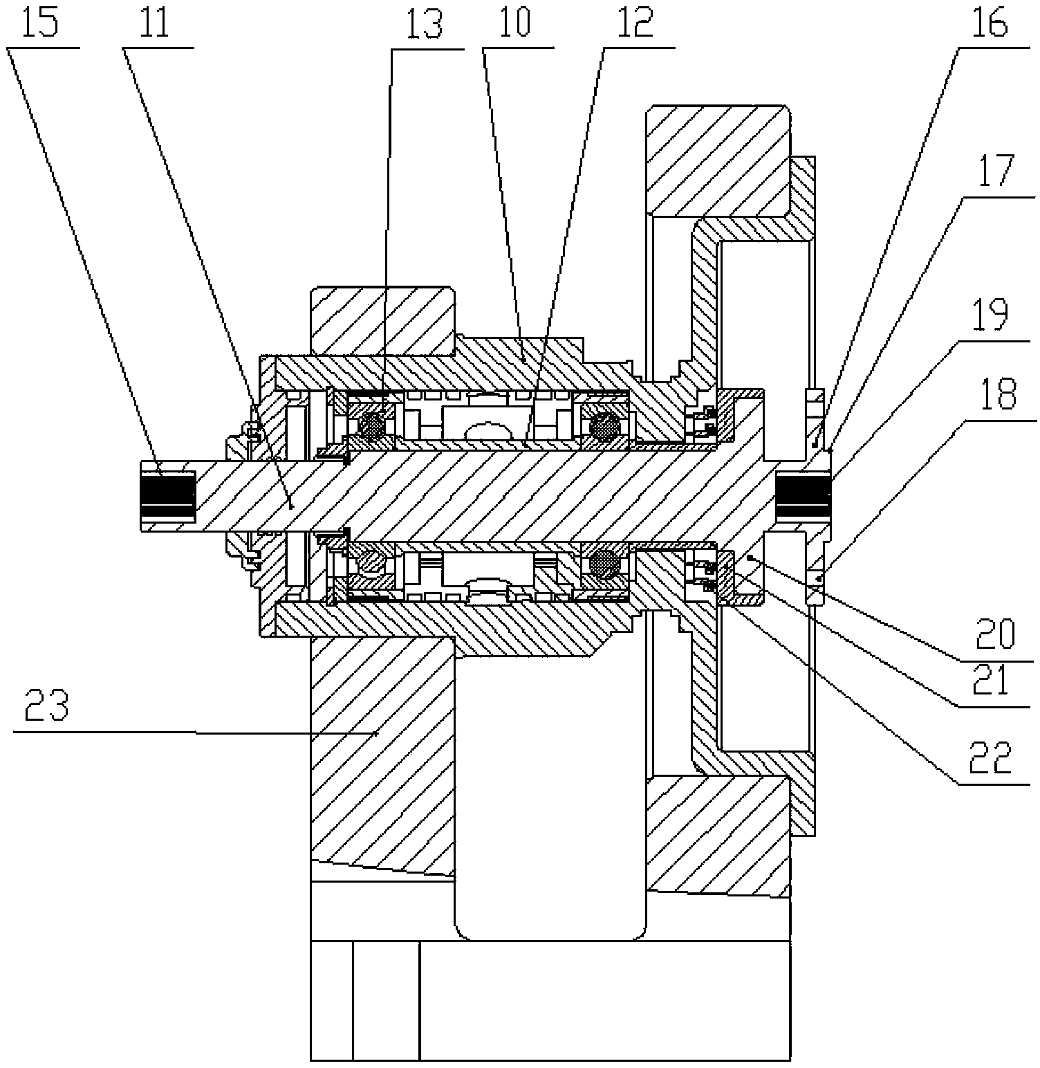
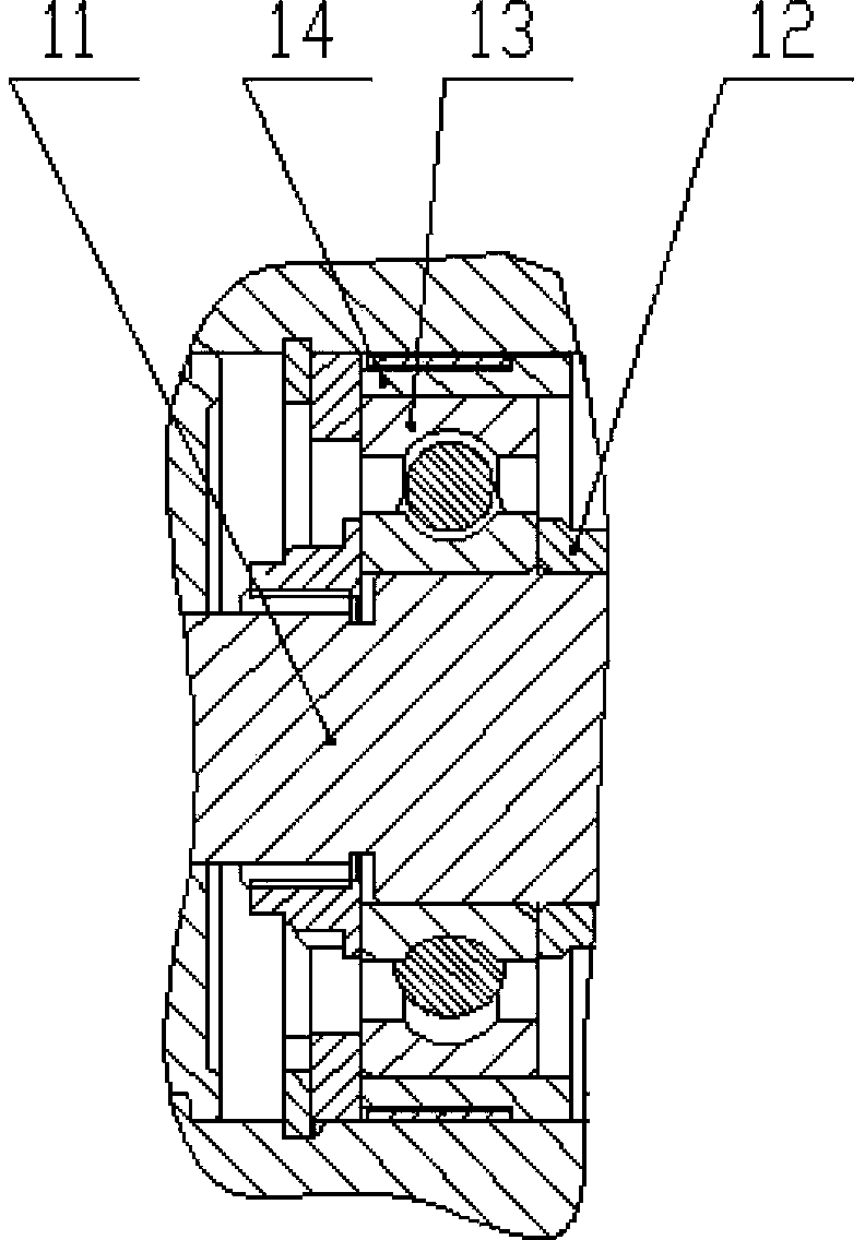
[0027] refer to figure 2 , the transition rotor part 5 includes a casing 10, a shaft 11, a sleeve 12 installed in the middle of the shaft 11, and support bearings 13 installed on both sides of the sleeve 12, and the support bearings 13 are positioned and axial...


PUM


Abstract

The invention discloses a mechanical vibration signal vibration-damping and filtering device for a high-speed gear box. The mechanical vibration signal vibration-damping and filtering device comprises a motor, wherein the output of the motor is connected with an experimental member through a transition rotor part, the transition rotor part comprises a shell, a shaft, a sleeve arranged on the middle of the shaft, and support bearings arranged on two sides of the sleeve; an elastic ring is arranged outside each support bearing, a lug boss of an inner ring of each elastic ring is in contact with the support bearings, a lug boss of an outer ring of each elastic ring is in contact with the shell, the end, which is close to a spline coupler, of the shaft,is provided with a first involute inner spline, the end, which is close to a thin-walled sleeve coupler, of the shaft is provided with a flange, a lug boss and a bolt hole are arranged on the flange, the end face of the flange is provided with a second involute inner spline, a thrust plate is arranged on the shaft, a molybdenum ring is embedded on the thrust plate, and a graphite ring paired with the molybdenum ring is arranged on an integral large base outside the shell. The mechanical vibration signal vibration-damping and filtering device is used in high-speed vibration damping, can be configured with multiple types of couplers, and has flexibility and stronger independence.

Description

technical field [0001] The invention belongs to the technical field of high-speed vibration damping equipment, and in particular relates to a vibration damping filter device for mechanical vibration signals of a high-speed gear box. technical background [0002] The vibration problem of high-speed rotating machinery has always been a hot spot of concern, especially the signal output from the high-speed gearbox contains a variety of harmonic vibration signals, which interfere and affect the experimental results. The commonly used vibration reduction method is to use a shock absorber to separate the possible vibration from the frame, such as rubber shock absorber, damping spring shock absorber, etc. Although this type of shock absorber has a simple structure and low price, it is not independent. Strong, lacks flexibility, needs to be installed on the test piece or on the test piece base, may change the structure of the test piece, and the vibration reduction can only be perfor...

Claims


Application Information

Patent Timeline
Patent Type & Authority Patents(China)
IPC IPC(8): F16F15/00
Inventor 耿海鹏高宇飞杨柏松虞烈冯圣
Owner XI AN JIAOTONG UNIV
Learn More