
A method for improving the carrying capacity of rack and pinion lifting device of self-elevating platform

A self-elevating platform, rack and pinion technology, applied in the direction of portable lifting devices, hoisting devices, transmission devices, etc., can solve the problems of reducing the size of contact surface stress, fatigue damage of rack and pinion, stress concentration, etc., to achieve the maximum Effect of Contact Stress Reduction

Inactive Publication Date: 2016-02-24
SHANDONG KERUI MACHINERY MFG +1
View PDF5 Cites 0 Cited by
  • Summary
  • Abstract
  • Description
  • Claims
  • Application Information

AI Technical Summary

Problems solved by technology

In the traditional rack and pinion lifting mechanism, the phase angles between different active pinions are the same. Under different meshing states, the contact surface stress between the active pinion and the rack and the bending stress of the pinion change greatly. Under the action of alternating stress, it is easy to Cause fatigue damage to the rack and pinion; and in order to prevent the rack and pinion from slipping when meshing, it is generally required that the tooth width of the gear is greater than the tooth width of the rack. The rack should not be widened to reduce the contact surface stress. At the same time, the maximum contact stress Occurs at both ends of the contact part of the rack, prone to stress concentration

Method used


Image

  • A method for improving the carrying capacity of rack and pinion lifting device of self-elevating platform
  • A method for improving the carrying capacity of rack and pinion lifting device of self-elevating platform
  • A method for improving the carrying capacity of rack and pinion lifting device of self-elevating platform

Examples


Embodiment Construction

[0024] The present invention will be further described below in conjunction with the accompanying drawings and embodiments.

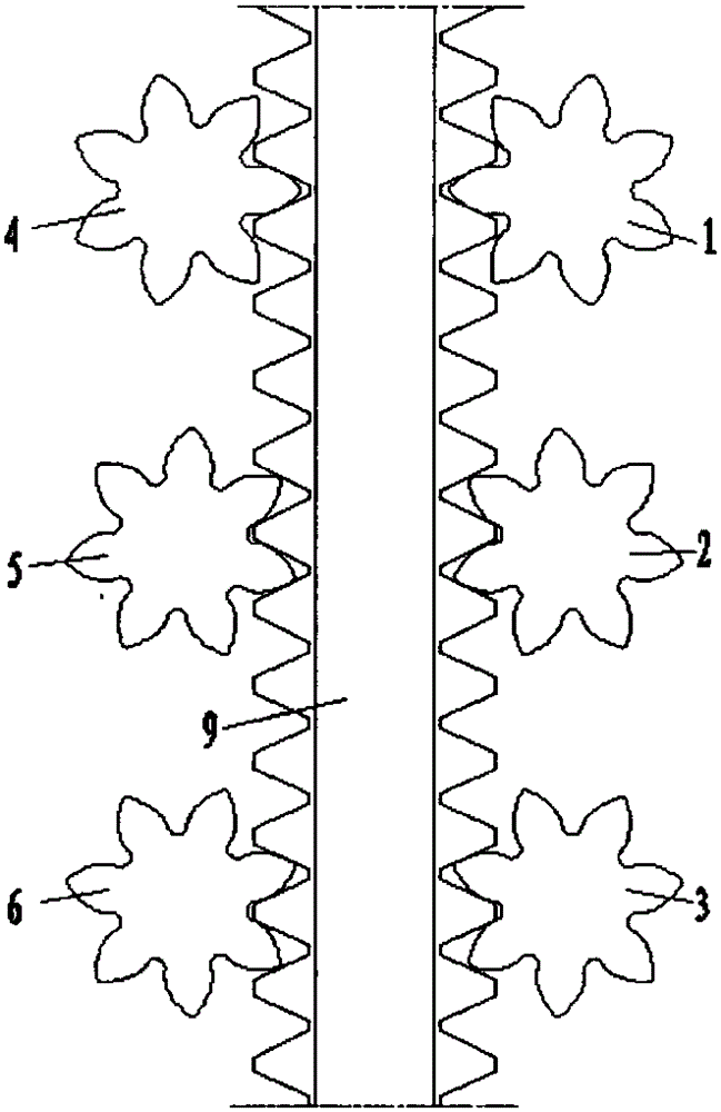
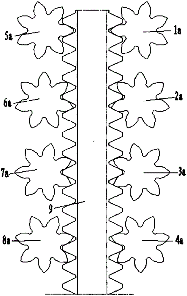
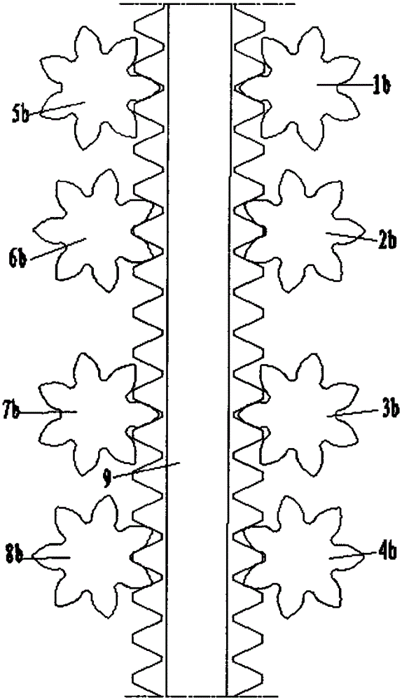
[0025] refer to figure 1 It is a schematic diagram of an embodiment in which the lifting mechanism is composed of three sets of driving pinion gear sets. Because the number of driving pinions on one side of the rack in the lifting mechanism is odd, the phase difference between adjacent driving pinions is 360 / (7x3)=17.14 ° , that is, between driving pinion 1 and driving pinion 2, between driving pinion 2 and driving pinion 3, between driving pinion 4 and driving pinion 5, and between driving pinion 5 and driving pinion 6 The phase difference is about 17.14 ° . The phase angle between the driving pinions at the same position on the opposite side of the rack is the same, so that the two horizontal radial forces generated by the two driving pinions are equal in size and opposite in direction to cancel each other.

[0026] There is an equal phase differe...


PUM

PropertyMeasurementUnit
Chamfer radiusaaaaaaaaaa

Abstract

The invention relates to a method and a measure for improving the carrying capability of a lifting device of a self-elevating type platform gear rack. The main method and the measure are as follows: according to the number n of driving pinions arranged at single side of a rack of the lifting device, the engagement phase difference of the adjacent driving pinions and the rack is reasonably set to be 360 / 7n (n is the odd number or the even number) or 25.71 degrees (i.e. 360 / 14, only n is the even number), and meanwhile, the contact edge of the rack is subjected to right-angle chambering or round corner chambering, wherein the driving pinions in the lifting device adopt the tooth form with great modulus and high deflection. After the method and the measure are adopted, the maximum stress during the single-tooth engagement of the gear rack can be reduced to a great degree, and the problem of stress concentration at the contact surface of the rack is solved, so the stress state of the gear rack of the lifting device is improved, and the service life is greatly prolonged.

Description

technical field [0001] The invention relates to a method and measures for improving the carrying capacity of a jack-and-pinion lifting device of a self-elevating ocean platform, and belongs to the field of ocean engineering. Background technique [0002] The jack-up platform refers to the equipment used for offshore oil and gas development or to serve offshore oil and gas development. It has the advantages of strong positioning ability, good mobile operation stability, and low cost. It has become the main force of continental shelf oil exploration and development. The relative movement of rising or falling between the main hull and the legs is its biggest feature. At present, there are two main lifting methods for self-elevating platforms: 1. The hydraulic cylinder jacking method, through the mutual cooperation of the main and auxiliary hydraulic cylinders, the lifting of the platform is realized. However, due to the inability to achieve continuous lifting, there are disadv...

Claims


Application Information

Patent Timeline
IPC IPC(8): F16H19/04F16H55/26F16H55/17E02B17/08
CPCE02B17/0818
Inventor 杨宪杨玉生刘化国陈国明岳吉祥王运安王涛信欣古仁龙刘睿
Owner SHANDONG KERUI MACHINERY MFG
Learn More