Solar panel roof installation structure and installation method thereof

The technology of a solar panel and an installation structure is applied in the field of solar energy application and can solve the problems of shortening the service life of the solar water heater, increasing the fatigue strength of the solar thermal collector, and inconvenience.

Active Publication Date: 2013-03-27
河北黑瓷老人太阳能科技有限公司
View PDF5 Cites 11 Cited by
  • Summary
  • Abstract
  • Description
  • Claims
  • Application Information

AI Technical Summary

Problems solved by technology

This brings difficulties to the installation of the solar collector. If it is not adjusted accurately, it will not only affect the thermal efficiency of the solar collector after installation, but may also increase the fatigue strength of the solar collector, thereby shortening the service life of the solar water heater
[0005] In addition, the roof of existing buildings has multiple structural layers, usually including concrete layer, thermal insulation material layer, cement mortar leveling layer, asphalt waterproof layer and cement mortar protective layer. Each structural layer plays an indispensable role, so Construction industry standards usually state that slotting and drilling of floor slabs are not allowed
The existing solar water heater installation methods are to fix the collector by bolts, anchor piles and other structures, which will cause varying degrees of damage to the structure and waterproof of the building, affect the life of the building, and even pose a safety hazard
[0006] This shows that the above-mentioned existing solar collector roof installation structure and installation method thereof obviously still have inconvenience and defects in structure, method and use, and need to be further improved urgently

Method used


Image

  • Solar panel roof installation structure and installation method thereof
  • Solar panel roof installation structure and installation method thereof
  • Solar panel roof installation structure and installation method thereof

Examples


Embodiment Construction

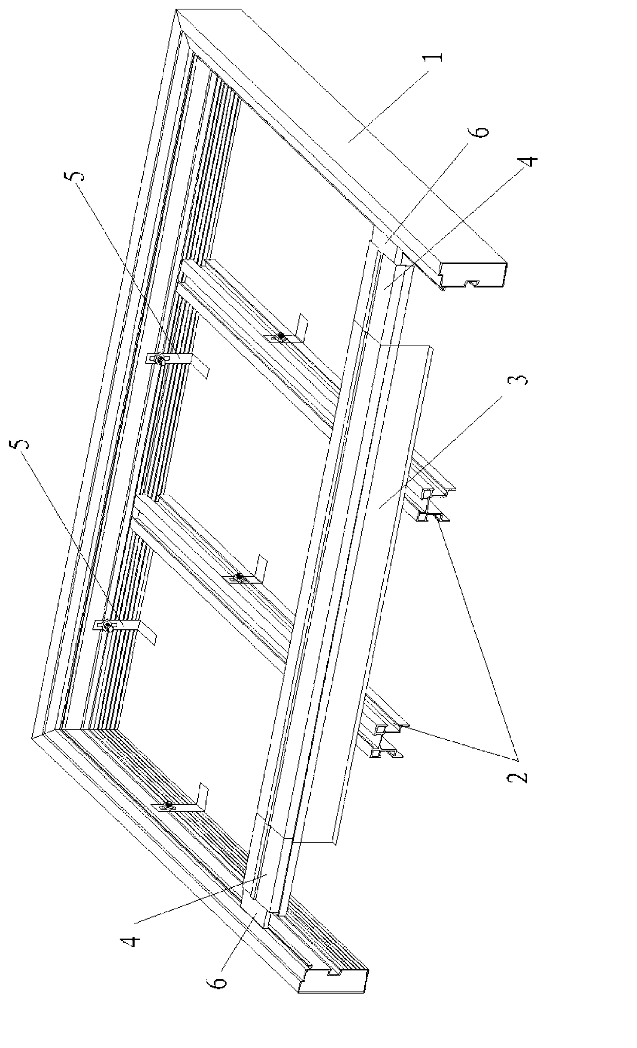
[0027] see figure 1 As shown, the roof installation structure of the solar panel of the present invention mainly includes a frame 1, a longitudinal keel 2, a transverse keel 3, a connecting piece 5 and a glass cover plate.

[0028] Wherein, the connector 5 of the present invention is an L-shaped 90-degree steel part, and its horizontal plane is fixed with the roof embedded parts by means of welding, etc., and a screw hole is opened on the vertical plane for fixing the frame 1 and the longitudinal keel 2 on the roof superior. Preferably, the screw hole of the connecting piece 5 is an elongated hole, which is about 20-50 mm long in the vertical direction, so that the frame 1, the longitudinal keel 2 and the The pitch of the roof, so as to ensure that the solar panels can be installed on the same plane exactly.

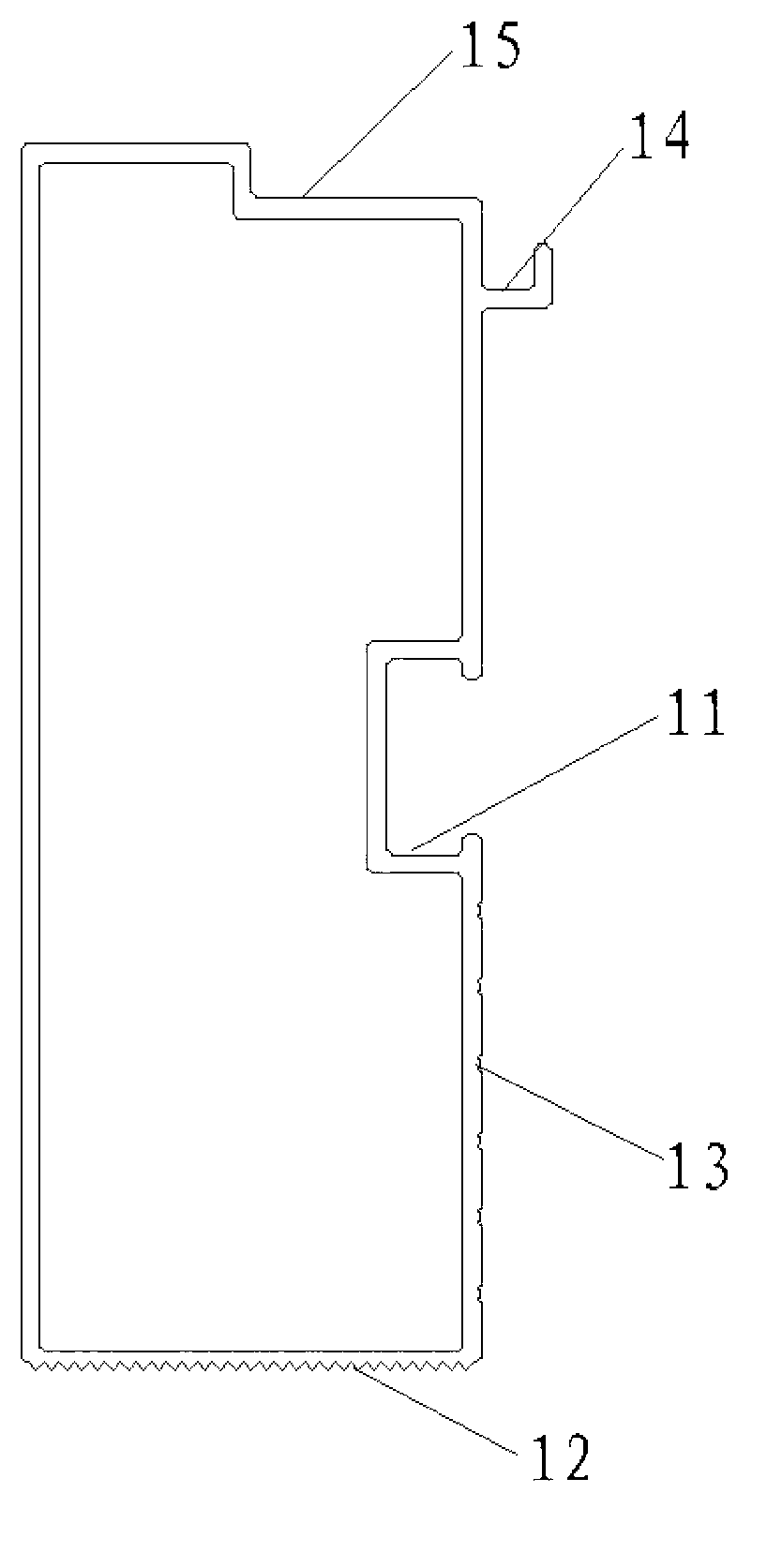
[0029] Please refer to figure 2 As shown, the inner side of the frame 1 is provided with a hook groove 11, and the screw 7 with the screw cap located in the hook gro...


PUM


Abstract

The invention relates to a solar panel roof installation structure and an installation method thereof. The installation structure comprises an L-shaped connecting piece, a frame, more than two longitudinal keels, more than one horizontal keel and a glass cover plate, wherein the frame is fixedly connected with the vertical surface of the connecting piece and fixedly connected with a roof embedded part through the horizontal surface of the connecting piece; the longitudinal keels are positioned in the frame, fixedly connected with the vertical surface of the connecting piece and fixedly connected with the roof embedded part through the horizontal surface of the connecting piece; the horizontal keels are arranged above the longitudinal keels; and the glass cover plate is arranged above the frame and the horizontal keels. The installation method comprises the following steps of: determining the mounting position of the frame according to the distribution condition of roof embedded iron, and fixing through the connecting piece; fixing the longitudinal keels; fixing the horizontal keels; paving heat-insulating materials, and placing a solar panel; and connecting pipelines, paving the glass cover plate, and sealing. The solar panel roof installation structure disclosed by the invention can not damage any structural layer of a roof and can greatly increase the construction efficiency on the basis of realizing the accurate installation of the solar panel.

Description

technical field [0001] The invention relates to the technical field of solar energy application, in particular to a roof installation structure of a solar panel and an installation method thereof. Background technique [0002] With the development of society and technology, the demand for energy is increasing. The development and utilization of renewable energy such as solar energy, wind energy, and tidal energy to replace traditional resources as much as possible has become an important direction for the development of various fields in various countries. [0003] In the field of solar energy utilization, solar water heaters are currently the most widely used products with the most mature technology and the best economy. Existing solar water heaters can be divided into glass vacuum tube solar water heaters and flat plate solar water heaters according to their heat collecting parts. Among them, the thermal efficiency of the glass vacuum tube solar water heater is relatively...

Claims


Application Information

Patent Timeline
Patent Type & Authority Applications(China)
IPC IPC(8): F24J2/52
CPCY02B10/20Y02E10/47
Inventor 王占平周文济曹树梁李永林张允宁王东纯许建华李海东张雪卿聂兆美郭立峤李介英吕强王晓波郭建王璐鹏
Owner 河北黑瓷老人太阳能科技有限公司
Why Eureka
Try Eureka