Method and device for multi-dimensional detection of angle sensor

An angle sensor and detection device technology, applied in measuring devices, surveying and navigation, and optical devices, can solve problems such as inability to perform dynamic precision detection, improve work efficiency and detection accuracy, improve detection accuracy, and reduce detection costs Effect

Active Publication Date: 2013-03-27
BEIJING INSTITUTE OF TECHNOLOGYGY
View PDF3 Cites 8 Cited by
  • Summary
  • Abstract
  • Description
  • Claims
  • Application Information

AI Technical Summary

Problems solved by technology

[0004] The detection equipment is a static detection, which can detect the static accuracy of the angle sensor of 18

Method used


Image

  • Method and device for multi-dimensional detection of angle sensor
  • Method and device for multi-dimensional detection of angle sensor
  • Method and device for multi-dimensional detection of angle sensor

Examples


Embodiment 1

[0047] This embodiment is to perform static precision detection on the absolute angle sensor.

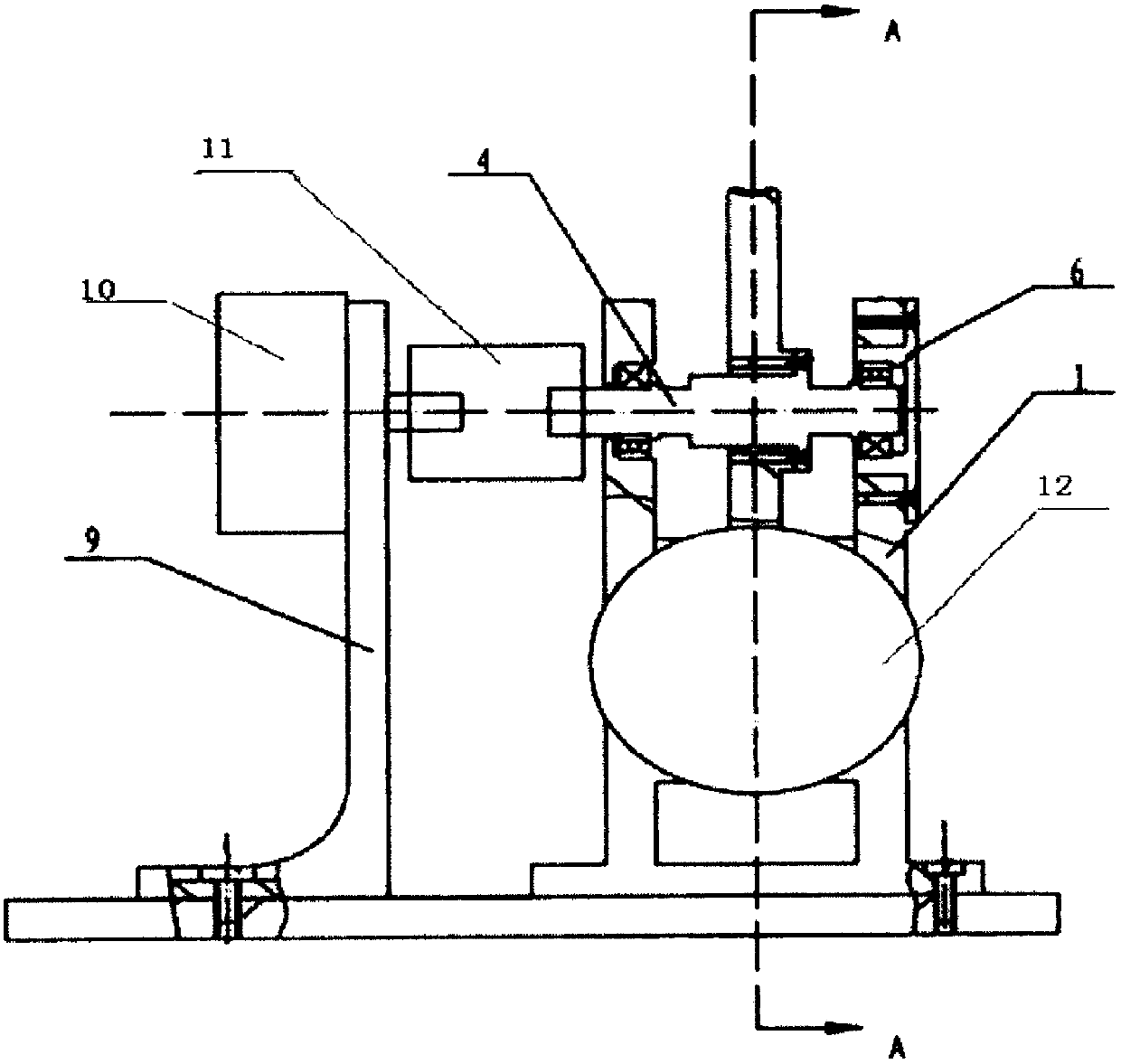
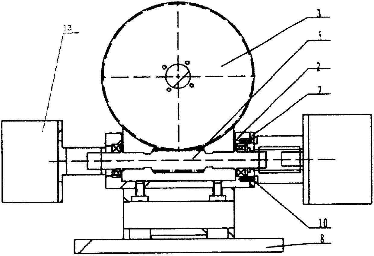
[0048] according to Figure 3 to Figure 6 Install the detection device in the connection mode shown, select the corresponding coupling and angle sensor mounting plate, and install the measured angle sensor on the corresponding mounting plate. Connect the appropriate data cables. Since the static accuracy test is performed in this example, it is necessary to connect the measured angle sensor to the output shaft decelerated by the worm gear. Since the absolute photoelectric encoder is selected for testing in this example, there is no requirement for the level or measurement method, so the detection device can be placed in any of the two placement methods, such as Figure 4 Placement as shown in , or flip the device 90 degrees along the A-A space.

[0049] Corresponding parameters are set on the industrial computer equipped with the special software of the present invention, such as...

Embodiment 2

[0057] This embodiment is to detect the dynamic accuracy of the planar electronic compass.

[0058] according to Figure 3 to Figure 6 Install the detection device in the connection mode shown, select the corresponding coupling and angle sensor mounting plate, and install the measured angle sensor on the corresponding mounting plate. Connect the appropriate data cables. Since the dynamic accuracy test is carried out in this example, and the electronic compass does not have high requirements for high-speed performance, the low-speed output shaft decelerated by the worm gear can be used for detection. Electronic compass accuracy detection needs to keep its level, so choose a horizontal detection plane (vertical output axis), such as Figure 4 For the installation method shown, use the leveling mechanism for leveling.

[0059] Corresponding parameters are set on the industrial computer equipped with the special software of the present invention, such as the type of the measure...


PUM


Abstract

The invention provides a method and device for multi-dimensional detection of an angle sensor. The method and device is used for performing high-accuracy static and dynamic accuracy detection on the angle sensor and can achieve accuracy detection of various angle sensors in a plurality of multi-axis planes. In the device, a closed-loop stepping motor is connected with one end of a worm B through a coupler, a detected angle sensor b is connected with the other end of the worm B through a coupler, a detected angle sensor a is connected with a revolving shaft through a coupler, the detected angle sensor a and the detected angle sensor b are both fixed outside a machine case through angle sensor installation bases, the revolving shaft is connected with a worm wheel A, the worm wheel A and the worm B are fixed inside the machine case through worm installation bases, the detected angle sensor a and the detected angle sensor b are both fixed outside a machine case through the angle sensor installation bases, a leveling structure is installed outside the machine case, and a computer controlling and processing unit is respectively connected with the closed-loop stepping motor, the detected angle sensor a and a detected angle sensor b through cables.

Description

technical field [0001] The invention relates to a multi-dimensional angle sensor detection method and device, belonging to the field of optomechanical integration. Background technique [0002] The angle sensor is a sensor that measures physical parameters such as the angular displacement of a rotating body. High-precision angle sensors are widely used in various fields such as industry, scientific research, and national defense. In order to clearly understand the measurement accuracy of the angle sensor, before the user uses it, high The precision measuring device conducts static precision and dynamic precision inspection on its precision. [0003] At present, there are several kinds of detection equipment for angle sensors at home and abroad, and the closest existing technology of the present invention is the angle sensor detection device developed by Beijing Institute of Technology Automation Institute, such as figure 1 and figure 2 Shown: is composed of body 1, worm m...

Claims


Application Information

Patent Timeline
IPC IPC(8): G01B21/22G01B11/26G01C17/38
Inventor 邓方王小刚蔡涛陈杰王艳永
Owner BEIJING INSTITUTE OF TECHNOLOGYGY
Why Eureka
Try Eureka