Dynamic balance device for blind hole part processing of slurry pump

A technology for parts processing and slurry pump, applied in the field of parts processing, can solve the problem of not being able to provide a balancing device, and achieve the effects of a wide range of weight, strong safety and reliability, and a wide range of adaptability

Active Publication Date: 2015-03-18
湖北省天门泵业有限公司
View PDF6 Cites 0 Cited by
  • Summary
  • Abstract
  • Description
  • Claims
  • Application Information

AI Technical Summary

Problems solved by technology

[0002] The dynamic balancing machines on the market generally place the rotating parts in the middle of the rotating shaft to measure and remove the unbalance of the parts; for example, the impeller of the slurry pump is connected by blind holes and the material hardness is above HRC58. Measurement and adjustment of parts , the market cannot provide a balancing device; therefore it is necessary to improve on this basis

Method used


Image

  • Dynamic balance device for blind hole part processing of slurry pump
  • Dynamic balance device for blind hole part processing of slurry pump
  • Dynamic balance device for blind hole part processing of slurry pump

Examples


Embodiment Construction

[0017] Attached below figure 1 to attach Figure 4 Examples of the present invention are illustrated, but not limited to the following examples:

[0018] A dynamic balance device for processing blind hole parts of a slurry pump is provided, which is composed of a bracket support component, a dynamic balance cutting component and the electric control cabinet component.

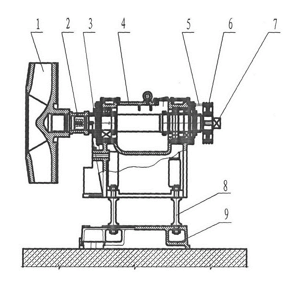
[0019] see figure 1 and figure 2 , the bracket support assembly includes a machine beam 8 arranged on the base 9, a bracket 4 is arranged on the machine beam 8, a rotating shaft 7 is arranged inside the bracket 4, and a joint is arranged at one end of the rotating shaft 7 2. The joint 2 is used to connect the rotating part 1, such as the impeller of the slurry pump; the other end of the rotating shaft 7 is connected to the pulley 6; the pulley 6 is used to drive the rotating shaft 7 and the rotation connected with the joint 2 The part 1 rotates together; the bracket 4 is also provided with a dial 3 corresp...


PUM


Abstract

A dynamic balance device for blind hole part processing of a slurry pump comprises a support bearing component, a dynamic balance cutting component and an electric control cabinet component in a matched manner. The support bearing component comprises bases, machine beams, a support, a rotary shaft, a joint, a rotating piece and a scale disc, and speed sensors and vibration sensors are arranged on the support. The dynamic balance cutting component comprises a cutting support, a motor and a grinding wheel, wherein the cutting support is arranged on a lever fulcrum shaft which is arranged on the other base and formed by connecting a bearing body with a central shaft. The electric control cabinet component comprises a frequency converter and a CAB510 electric box, the frequency converter is used for driving the motor to drive a belt pulley and the grinding wheel to rotate, and an input end of the CAB510 electric box is electrically connected with the speed sensors and the vibration sensors, an output end of the CAB510 electric box is electrically connected with the frequency converter and a display screen, and numerical variables displayed by the display screen correspond to unbalanced quantity of the rotor piece and angular coordinate position shown by the scale disc. The dynamic balance device is used for determining deweighing quantity and direction during processing the rotor piece.

Description

technical field [0001] The invention relates to the processing of parts in the field of pumps, such as a dynamic balancing device for processing rotating parts of the pump body, such as impellers; the invention is especially suitable for the dynamic balance test and adjustment of blind hole parts and general rotating parts, making it A rotor that is rotationally balanced. Background technique [0002] The dynamic balancing machines on the market generally place the rotating parts in the middle of the rotating shaft to measure and remove the unbalance of the parts; for example, the impeller of the slurry pump is connected by blind holes and the material hardness is above HRC58. Measurement and adjustment of parts , the market cannot provide a balancing device; thus it is necessary to improve on this basis. Contents of the invention [0003] The object of the present invention is to provide a dynamic balance device for processing blind hole parts of a slurry pump. [0004]...

Claims


Application Information

Patent Timeline
Patent Type & Authority Patents(China)
IPC IPC(8): G01M1/38
Inventor 王江祥杨国新张利军朱遂高
Owner 湖北省天门泵业有限公司
Why Eureka
Try Eureka