
Method for positioning optic disk for eye fundus image on basis of PC (Phase Congruency)

A fundus image and positioning method technology, applied in fundus mirrors, ophthalmic treatment and other directions, can solve the problems of inconsistent optic disc size, unable to obtain positioning results, affecting positioning results, etc., to improve the accuracy and efficiency of diagnosis, and improve the level of medical diagnosis. , the effect of expanding the scope of application

Inactive Publication Date: 2013-04-03
TIANJIN POLYTECHNIC UNIV
View PDF3 Cites 12 Cited by
  • Summary
  • Abstract
  • Description
  • Claims
  • Application Information

AI Technical Summary

Problems solved by technology

The first type of method locates the optic disc based on the roughly circular structure of the optic disc and its higher brightness relative to other parts of the fundus. For retinas with lesions, this method is not robust, especially for those with fundus diseases. situation, this method cannot achieve good positioning results
In addition, most of these methods first remove fundus blood vessels through morphological preprocessing methods. However, morphological preprocessing uses globally unified and fixed morphological structural elements, and morphological transformations are inherently nonlinear and irreversible, so it is inevitable Introduce large changes to the optic disc edge features, resulting in inaccurate positioning results
The second type of method is based on the property that the optic disc is the converging point of the retinal vascular network, which needs to segment the blood vessels in advance, has high requirements for the extraction accuracy of the vascular network, and has high computational complexity, and is only suitable for retinal images with clear vascular networks. Difficult to achieve optic disc positioning under different image quality
[0005] The background of the fundus image is complex, the contrast between the optic disc and the background is low, the illumination is uneven, and the size of the optic disc is not uniform and other factors will affect the positioning results, resulting in inaccurate positioning or even target loss

Method used


Image

  • Method for positioning optic disk for eye fundus image on basis of PC (Phase Congruency)
  • Method for positioning optic disk for eye fundus image on basis of PC (Phase Congruency)
  • Method for positioning optic disk for eye fundus image on basis of PC (Phase Congruency)

Examples


Embodiment Construction

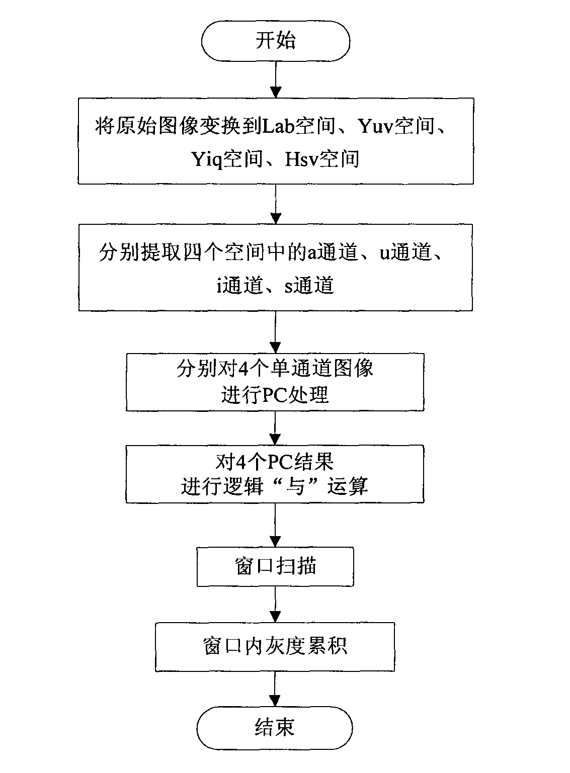
[0022] The flow chart of the present invention is as figure 1 As shown, firstly, to highlight the optic disc, the original image is transformed into the four color spaces of Lab, Yuv, Yiq, and Hsv; a single-channel image is selected in each space for PC processing, and the processing result is enhanced by logical "AND" operation; Scanning and gray-scale accumulation methods locate the optic disc. The specific implementation process of the technical solution of the present invention will be described below in conjunction with the accompanying drawings.

[0023] 1. Color space channel selection:

[0024] Select the a channel of Lab space, the u channel of Yuv space, the i channel of Yiq space and the s channel of Hsv space. like figure 2 As shown, after transforming the original image to these 4 channels, the optic disc is obviously prominent and maintains good edge characteristics, which is beneficial to the subsequent positioning of the optic disc.

[0025] 2. Process the...


PUM


Abstract

The invention belongs to the field of medical image treatment and relates to a method for positioning an optic disk for an eye fundus image on the basis of PC (Phase Congruency). According to the method, after four relatively prominent single-channel images for the optic disk are selected, a PC function is utilized to treat the selected images, and a logic AND is adopted for enhancing a result. The window scanning and the gray level accumulation are performed on the eye fundus image subjected to the enhancing treatment, so that the optic disk is positioned. The method is not influenced by the noise, luminance and contrast change in the images and is high in accuracy in positioning the optic disk for the eye fundus images of normal fundus, and slight and moderate as well as severe diabetes mellitus lesion.

Description

technical field [0001] This patent relates to a method for locating the optic disc in fundus images based on phase consistency. This method can determine the position of the optic disc in the fundus image, and has high accuracy for normal fundus and fundus images of mild, moderate and severe diabetic lesions. The invention belongs to the technical field of image processing and can be applied to clinical ophthalmology and the diagnosis and treatment of diseases related to fundus lesions. Background technique [0002] Medical image processing and analysis has always been a focus and hot issue in the field of image processing and analysis. With the powerful means of graphics and image technology, the quality and display methods of medical images have been greatly improved, which has greatly improved the level of diagnosis and treatment. Image processing technology has been introduced into the Department of Ophthalmology for many years. Through the calculation and analysis of f...

Claims


Application Information

Patent Timeline
Patent Type & Authority Applications(China)
IPC IPC(8): A61B3/12A61F9/00
Inventor 肖志涛耿磊张芳吴骏李筱涵
Owner TIANJIN POLYTECHNIC UNIV
Learn More