Collapsible power assembly for coiler mandrel

A powertrain and machine reel technology, applied in the field of expansion and contraction powertrain, can solve the problems of increasing the axial size of the expansion and contraction powertrain, not being able to adapt to the axial installation space, complex structure, etc., to achieve volume reduction, shaft The effect of decreasing the axial length and reducing the overall axial length

Inactive Publication Date: 2013-04-03
JINYANG ELECTROMECHANICAL EQUIP MFG HUNAN
View PDF4 Cites 2 Cited by
  • Summary
  • Abstract
  • Description
  • Claims
  • Application Information

AI Technical Summary

Problems solved by technology

[0003] This kind of reel expansion and contraction power assembly of the coiler has the following disadvantages: In order to connect the rod portion of the pull rod 2 and the piston 5 of the expansion and contraction cylinder through the connecting piece 51, the pull rod 2 must extend out of the main shaft 1 for a certain distance to provide a connection with the piston. 5. The connecting part of the rod part increases the axial size of the expansion and contraction power assembly, which cannot adapt to the harsh axial installation space for the coiler reel provided by some steel factories; in addition, in order

Method used


Image

  • Collapsible power assembly for coiler mandrel
  • Collapsible power assembly for coiler mandrel

Examples


Example Embodiment

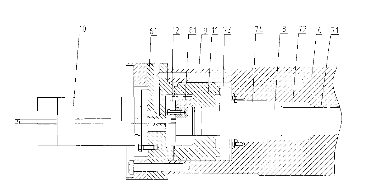
[0016] like figure 2 As shown, an expansion and contraction power assembly for a coiler reel includes a tie rod 8 installed in the shaft hole of the main shaft 6, an expansion and contraction oil cylinder 9 integrated with the main shaft 6, and an expansion and contraction oil cylinder 9 installed on the main shaft 6 The rotary joint 10 on the side end surface of the back main shaft 6, the shaft hole of the main shaft 6 is in the shape of a step with a diameter gradually increasing from the expansion and contraction cylinder 8 to the rotary joint 10, and is divided into a first shaft hole 71, a second shaft hole 72 and a second shaft hole in turn. Three shaft holes 73, most of the tie rod 2 are located in the first shaft hole 71 and the second shaft hole 72, the third shaft hole 73 is the oil chamber of the expansion and contraction cylinder 9, and the oil chamber of the expansion and contraction cylinder 9 is equipped with a piston 11. There is a through hole in the center o...


PUM


Abstract

The invention relates to a collapsible power assembly for a coiler mandrel. The collapsible power assembly comprises a pull rod 8 installed in shaft holes of a main shaft 6, a collapsible oil cylinder 9 connected with the main shaft 6 to form a whole body, and a rotating connector 10 installed on the side end face of the main shaft 6 on the back of the collapsible oil cylinder 9. A first shaft hole 71, a second shaft hole 72 and a third shaft hole 73 are respectively formed in the main shaft 6 from the collapsible oil cylinder 8 to the rotating connector 10. The third shaft hole 73 serves as an oil chamber of the collapsible oil cylinder 9. The oil chamber of the collapsible oil cylinder 9 is internally provided with a piston 11. A through hole through which the pull rod 8 penetrates is formed in the center of the piston 11. A bottom cover 61 of the collapsible oil cylinder 9 is fixedly installed on the end face, facing to the rotating connector 10, of the main shaft 6 by a bolt. The rotating connector 10 is coaxially fixed on the bottom cover 61 through a bolt. The axial length of the pull rod and the piston is greatly shortened, so that the overall axial length of the collapsible power assembly for the coiler mandrel is shortened, the parts are reduced, and the structure is simplified. Therefore, the connection between a compressing nut and the pull rod is effectively prevented from loosening.

Description

technical field [0001] The invention relates to a coiler reel, in particular to an expansion and contraction power assembly for the coiler reel. Background technique [0002] The structure of the existing reel expansion and contraction power assembly of the coiler is as follows: figure 1 As shown, it includes a pull rod 2 coaxial with the main shaft 1, an expansion and contraction oil cylinder 3 and a rotary joint 4, and the rotary joint 4 is fixedly installed on the end face of the expansion and contraction oil cylinder 3 on the side opposite to the main shaft 1 to control the supply of hydraulic oil in the expansion and contraction oil cylinder 3. The piston 5 located in the oil chamber of the expansion and contraction cylinder 3 can move back and forth along the axial direction of the main shaft 1, and the rod part of the piston 5 is connected with the pull rod 2 in the shaft hole of the main shaft 1 through the connecting piece 51, and the pull rod 2 drives the movement ...

Claims


Application Information

Patent Timeline
IPC IPC(8): B21C47/30
Inventor 陈新刚李焱琦胡世标
Owner JINYANG ELECTROMECHANICAL EQUIP MFG HUNAN
Why Eureka
Try Eureka