Hydraulic punching and flanging mould used for interior high-pressure forming member

An internal high pressure forming and flanging mold technology, applied in forming tools, manufacturing tools, metal processing equipment, etc., can solve the problem of wasting cleaning time, difficult to remove the flanging inserts of the tube blank to be formed in the blanking area, reducing production efficiency, etc. problems, to achieve the effect of improving production efficiency, simple structure, and saving cleaning time

Active Publication Date: 2013-04-03
HARBIN INST OF TECH
View PDF8 Cites 6 Cited by
  • Summary
  • Abstract
  • Description
  • Claims
  • Application Information

AI Technical Summary

Problems solved by technology

[0004] The present invention solves the problems that the blanking area of ​​the hydraulic punching-flanging mold of the existing internal high-pressure forming part falls into the tube blank to be formed a

Method used


Image

  • Hydraulic punching and flanging mould used for interior high-pressure forming member
  • Hydraulic punching and flanging mould used for interior high-pressure forming member
  • Hydraulic punching and flanging mould used for interior high-pressure forming member

Examples


Example Embodiment

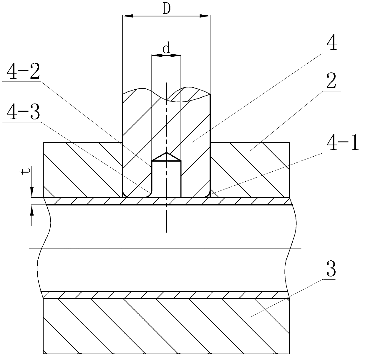
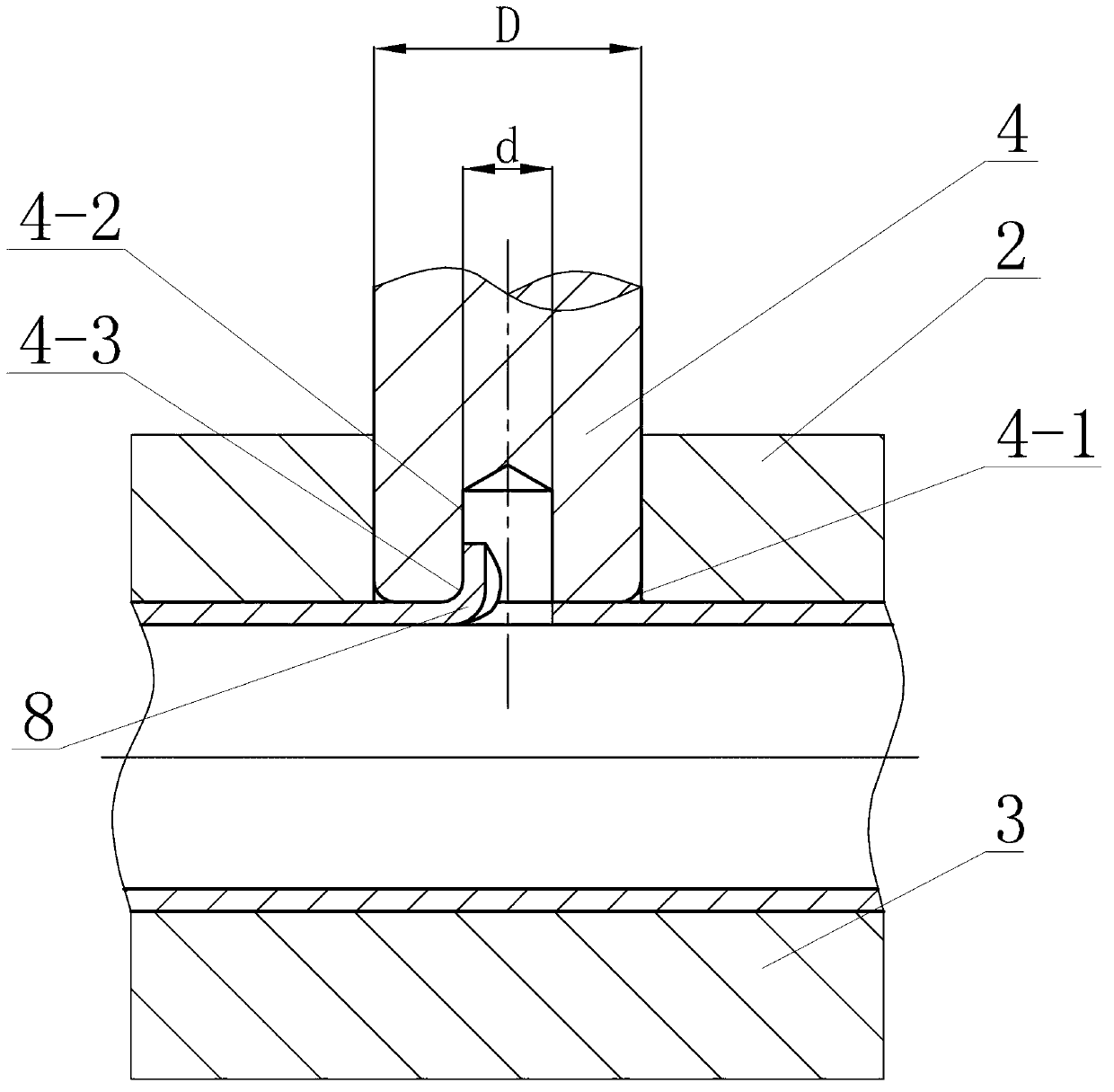
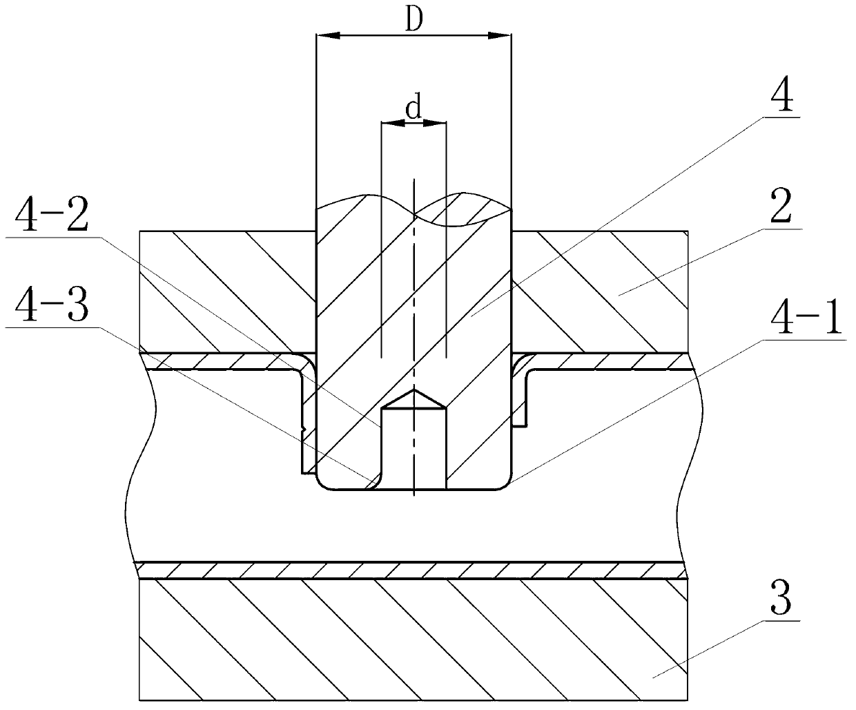
[0010] Specific implementation mode one: as Figure 1~3 As shown, the hydraulic punching-flange die for internal high-pressure formed parts of this embodiment includes an upper module 2, a lower module 3 and a punch 4, the upper module 2 is located on the upper end surface of the lower module 3, and the upper module 2 and The butt surface of the lower module 3 is machined along the length direction of the cavity of the tube blank to be formed. During internal high pressure forming, the tube blank to be formed is located in the cavity of the tube blank to be formed. Located in the punch hole, the outer edge of the lower end of the punch 4 has a first fillet 4-1, and the lower end of the punch 4 is processed with a central blind hole 4-2 along the axial direction, and the left half of the central blind hole 4-2 A second rounded corner 4-3 is processed, and the radii of the first rounded corner 4-1 and the second rounded corner 4-3 are both 0.8 to 2 times the wall thickness of th...

Example Embodiment

[0029] Specific implementation mode two: as Figure 4~6 As shown, the hydraulic punching-flange die described in this embodiment further includes a spring 14 and a mandrel 15, and the mandrel 15 is installed in the central blind hole 4-2 through the spring 14. In such a design, other components and connections are the same as those in the first embodiment.

[0030] When punching aperture , in order to ensure the forming of the transition fillet of the section of the internal high pressure forming part, the punch structure is designed as Figure 4~6 As shown, the outer diameter of the punch 4 is D, the inner diameter of the central blind hole 4-2 of the punch 4 is d, and the left half of the central blind hole 4-2 is processed with a second fillet 4-3. In order to prevent the internal pressure drop caused by the breakage of the blanking area 8 before the completion of the internal high pressure forming, a spring 14 and a mandrel 15 are installed in the central blind hole 4-2...

Example Embodiment

[0035] Embodiment 1: When punching hole diameter Time


PUM


Abstract

A hydraulic punching and flanging mould used for an interior high-pressure forming member relates to a hydraulic punching and flanging mould. The hydraulic punching and flanging mould solves the problems that a blanking region of the conventional hydraulic punching and flanging mould of the interior high-pressure forming member falls into a to-be-formed pipe blank, a flanging embedded block is difficult to take out, cleaning time is wasted and production efficiency is reduced. An upper mould block is located at the upper end face of a lower mould block; to-be-formed pipe blank cavities are machined on butting surfaces of both the upper mould block and the lower mould block along a length direction; the to-be-formed pipe blank is located in the to-be-formed pipe blank cavity during the interior high-pressure forming process; a punch pin hole is machined on the upper mould block; the lower end of the punch pin is located in the punch pin hole; a first filleted corner is chamfered at the outer edge of the lower end of the punch pin; a central blind hole is machined at the lower end of the punch pin along the axial direction; a second filleted corner is machined at the left half part of the central blind hole; and the radiuses of both the first filleted corner and the second filleted corner are 0.8-2 times the wall thickness of the to-be-formed pipe blank. The hydraulic punching and flanging mould is used for punching and flanging the interior high-pressure forming member.

Description

technical field [0001] The invention relates to a hydraulic punching-flange die. Background technique [0002] High pressure formed parts are common lightweight hollow components of automobile chassis and body. In order to assemble the high pressure formed parts with other parts, it is often necessary to process several to more than ten holes and flanging the holes to obtain a certain straight wall. Height, in order to process the internal thread for assembly, or for inlaying other parts. The hydraulic punching method is often used to make holes on the internal high pressure forming parts, which can shorten the production cycle, reduce the production cost and improve the positioning accuracy. The automobile sub-frame is a typical hydraulic punching internal high pressure forming part. For the holes that need to be flanged, the punching-flanging process from outside to inside is mostly used in the world at present, that is, after the inner high-pressure forming pipe wall is ...

Claims


Application Information

Patent Timeline
IPC IPC(8): B21D37/10
Inventor 刘刚郝晶苑世剑
Owner HARBIN INST OF TECH
Why Eureka
Try Eureka