Assembly phase control method of crank head connecting block for large-interference crank shear

A technology of phase control and connecting blocks, which is applied in the direction of manufacturing tools, metal processing, metal processing equipment, etc., can solve the problems of poor phase control, time-consuming and laborious rework, low installation success rate, etc., to achieve simple equipment, convenient operation, phase Control precise effects

CN103008969AActive Publication Date: 2013-04-03MCC SFRE HEAVY IND EQUIP
8 Cites 3 Cited by

Patent Information

Authority / Receiving Office
CN · China
Patent Type
Applications(China)
Current Assignee / Owner
Publication Date
2013-04-03

Smart Images

  • Figure 1
    Figure 1
  • Figure 2
    Figure 2
  • Figure 3
    Figure 3
Patent Text Reader

Abstract

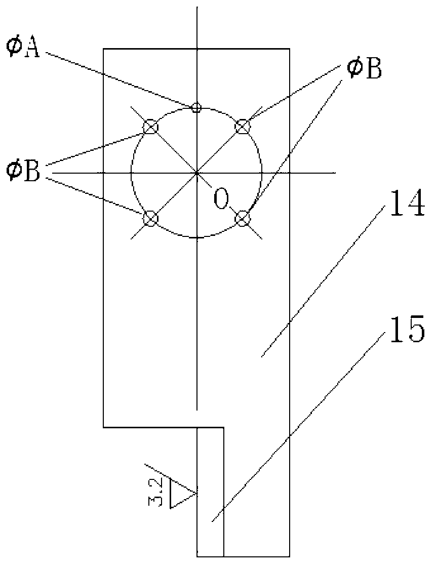
The invention discloses an assembly phase control method of a crank head connecting block for a large-interference crank shear. The assembly phase control method comprises the following steps of: 1. production of tooling; 2. on a connecting plate, according to the indexing size of the same position of four screw holes used for buckling with a gland on the outer end surface of an upper crank head connecting block, respectively marking out processing lines of four holes B corresponding to the four screw holes one by one; 3. connecting the tooling and the upper crank head connecting block by four screws into an assembly body in a buckling way; 4. processing holes A in the tooling and the upper crank head connecting block, and then putting dowels in the holes A; and an angle milling head milling the processing surface of a transverse plate on the tooling; 5. assembling a lower crank head connecting block, and then assembling the upper crank head connecting block, so that the Ra3.2mum processing surface of the transverse plate on the tooling can cling to a lower shear blade surface to slide; and 6. dismantling the tooling, and assembling other parts. According to the method provided by the invention, the phase can be precisely controlled, and the installation is successful once.
Need to check novelty before this filing date? Find Prior Art

Description

technical field

[0001] The invention belongs to the technical field of mechanical equipment manufacturing, and relates to a method for controlling the assembly phase of a crank head connecting block of a large surplus crank shear. Background technique

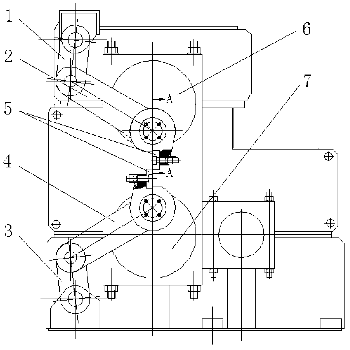
[0002] At present, a kind of crank shear is widely used in steel mills, and the structure diagram is as follows figure 1 , figure 2 As shown, due to the strict phase requirements between the upper and lower upper crank head connecting blocks, and the high margin requirements between it and the upper bushing of the transmission shaft, the problem encountered during assembly is how to Accurately control the phase relationship between the upper and lower crank head connecting blocks. Once the phase control is not good during assembly and the error is large, if you rework and disassemble it, the crank head connecting block will It is difficult to disassemble, which causes the cutting blades to fail to overlap and cannot be use...

Examples

Embodiment Construction

[0023] Such as figure 1 , figure 2 As shown, it is a schematic structural diagram of a crank shear that is often used in existing steel mills, including an upper crank head connecting block 6 and a lower crank head connecting block 7, wherein the upper crank head connecting block 6 is connected with the upper shear blade, and the lower crank head The head connecting block 7 is connected with the lower cutting edge, and the upper cutting edge and the lower cutting edge together form the cutting edge 5; the upper crank head connecting block 6 is sequentially connected with connecting rod two 2 and connecting rod one 1, and the lower crank head connecting block 7 is sequentially It is connected with connecting rod four 4 and connecting rod three 3;

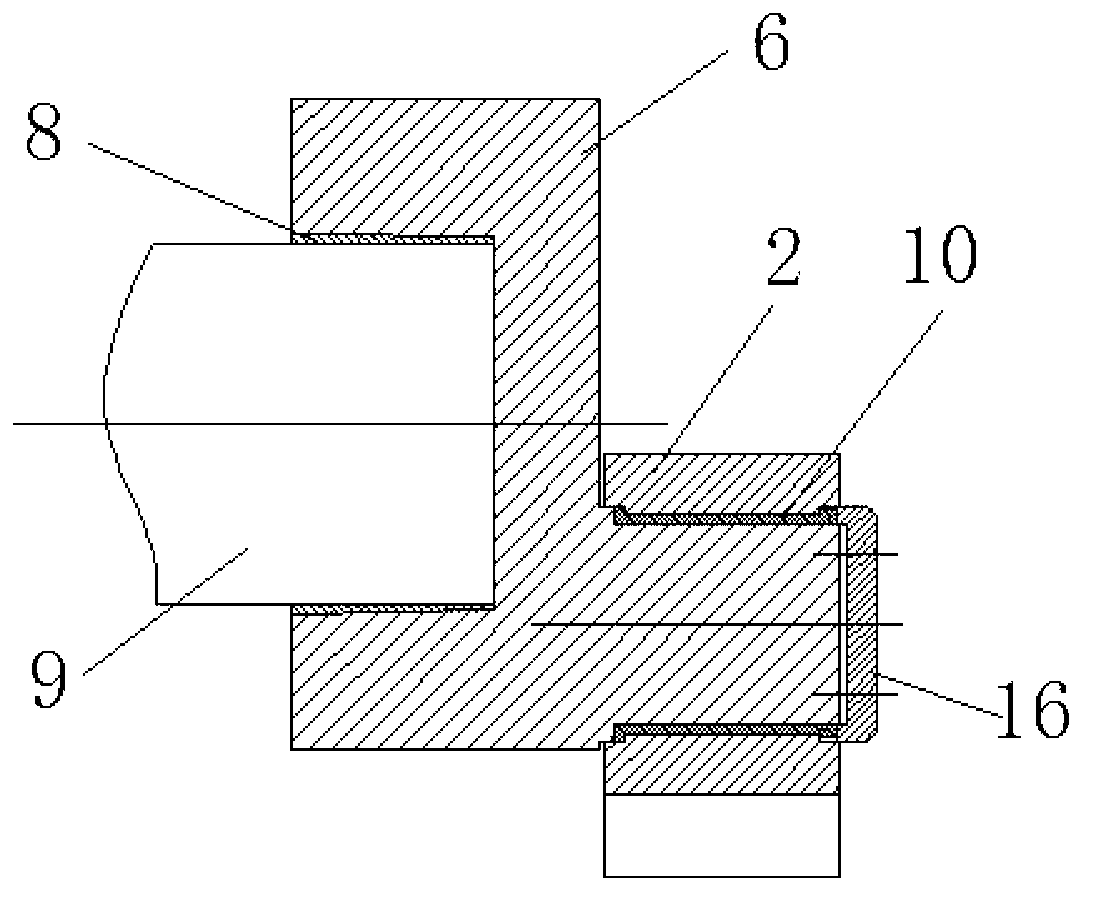
[0024] The outer side of the upper crank head connecting block 6 is connected with the connecting rod 2 through the outer bushing 10, and the inner end surface axis hole of the upper crank head connecting block 6 is connected with ...