Processing method of machine tool mobile support cross beam shaft, the machine tool mobile support cross beam shaft and special clamp of the machine tool mobile support cross beam shaft

A mobile support, special fixture technology, applied in manufacturing tools, metal processing equipment, abrasive jet machine tools, etc., can solve the problems of inability to guarantee accuracy, high processing costs, etc., to reduce processing costs, avoid the need, and reduce labor intensity and skills. desired effect

Active Publication Date: 2013-04-03
柔锋机械科技(江苏)有限公司
View PDF9 Cites 2 Cited by
  • Summary
  • Abstract
  • Description
  • Claims
  • Application Information

AI Technical Summary

Problems solved by technology

As a typical machine tool case is a high-pressure jet abrasive water jet cutting (referred to as water jet) machine tool, the cutting stroke is usually more than one meter long, and the working head needs to be positioned on the XYZ axis. If you want to obtain parallel and smooth straight The mobile support beam axis requires high processing costs, even so sometimes the accuracy cannot be guaranteed

Method used


Image

  • Processing method of machine tool mobile support cross beam shaft, the machine tool mobile support cross beam shaft and special clamp of the machine tool mobile support cross beam shaft
  • Processing method of machine tool mobile support cross beam shaft, the machine tool mobile support cross beam shaft and special clamp of the machine tool mobile support cross beam shaft
  • Processing method of machine tool mobile support cross beam shaft, the machine tool mobile support cross beam shaft and special clamp of the machine tool mobile support cross beam shaft

Examples


Embodiment Construction

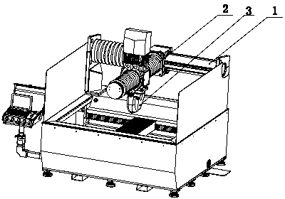
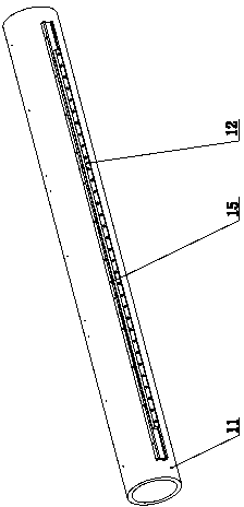
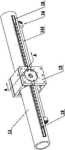
[0039] Such as Figure 1-5 As shown, the embodiment of the present invention is aimed at the application embodiment of the screw drive provided with the guide rail 12 on the beam shaft 11, wherein the groove supporting the guide rail 12 on the beam shaft 11 is constructed by a channel steel 15, and is provided with The screw mandrel 141 of the screw drive assembly 14 is parallel to the guide rail 12, that is, the screw drive assembly 14 is fixed on the beam shaft 11 and the screw mandrel 141 is below the beam shaft 11, and the screw mandrel 141 and the guide rail 12 are all parallel to the horizontal line. The channel steel 15 supporting the guide rail is fixedly connected to the side of the beam shaft 11, and the guide rail 12 is fixed at the placement cavity protruding from the channel steel 15. 131. Both sides of beam shaft 11 are evenly distributed with channel steel 15 ie its groove, beam shaft 11 adopts hollow steel pipe, screw motor 142 of screw drive assembly 14 and i...


PUM


Abstract

The invention discloses a processing method of a machine tool mobile support cross beam shaft, the machine tool mobile support cross beam shaft and a special clamp of the machine tool mobile support cross beam shaft. The processing method is characterized in that a side surface of a cross beam shaft is provided with a groove which is parallel to the axis and is used for supporting a guide rail; the cross beam shaft with the groove is arranged into the special clamp and the axis is allowed to be horizontal; a side clamp plate of the special clamp corresponding to the groove of the cross beam shaft is provided with a plurality of pairs of guide rail clamp blocks which are subject to standard horizontal correction; a guide rail is inserted into a travel cavity of the guide rail clamp block and a receiving cavity of the groove; the guide rail is fixed on the cross beam shaft through fasteners and the guide rail is allowed to be horizontal; and the special clamp is dismounted so that the cross beam shaft with the guide rail is obtained. According to the invention, the flatness and the parallelism of the guide rail of the processed mobile support cross beam shaft can be guaranteed, templated manufacture and repeated and convenient precision processing are realized, a corresponding processing cost is greatly reduced, a processing period is shortened, and stocks are reduced. The machine tool mobile support cross beam shaft disclosed herein is especially suitable for precision, light-load and long-axis occasions.

Description

technical field [0001] The present invention relates to a machine tool movable support beam shaft, its manufacturing method and a special fixture, in particular to a linear movable support beam shaft applied to a high-pressure water jet cutting machine tool, its manufacturing method and a special fixture. Background technique [0002] In the machine tool, if the working head needs to move accurately on the XYZ axis, it needs to be supported by the mobile support beam axis. The mobile support beam axis is also called a linear axis or directly called the X axis, Y axis, etc., and is used to support it. Walking working head or its horizontal sliding seat. The processing and forming of the movable support beam axis needs to ensure that it is parallel, smooth and straight. This requirement directly affects the dynamic performance of the entire machine tool and the machining accuracy of the parts, and the machining accuracy is the main factor affecting the application range of the...

Claims


Application Information

Patent Timeline
Patent Type & Authority Applications(China)
IPC IPC(8): B24C3/02B24C5/00B24C9/00
Inventor 曾继跃
Owner 柔锋机械科技(江苏)有限公司
Why Eureka
Try Eureka