Method for operating a dual accumulator vehicle circuit

A technology of dual accumulators and accumulators, applied in the direction of circuit devices, battery circuit devices, circuits or fluid pipelines, etc., can solve problems such as troublesome costs

Active Publication Date: 2017-09-12
ROBERT BOSCH GMBH +1
View PDF5 Cites 0 Cited by
  • Summary
  • Abstract
  • Description
  • Claims
  • Application Information

AI Technical Summary

Problems solved by technology

However, such measures are cumbersome and always entail additional costs

Method used


Image

  • Method for operating a dual accumulator vehicle circuit
  • Method for operating a dual accumulator vehicle circuit
  • Method for operating a dual accumulator vehicle circuit

Examples


Embodiment Construction

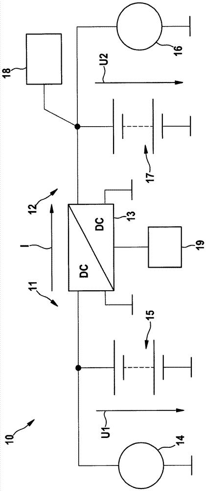
[0026] figure 1 A dual-accumulator vehicle circuit of a motor vehicle is shown, which can be operated by means of a method according to a particularly preferred embodiment of the invention.

[0027] The vehicle circuit with dual accumulators is generally indicated by 10 . It comprises two partial circuits 11 , 12 connected to one another by means of a DC transformer 13 . A generator 14 is provided in the first partial circuit 11 , which is provided for directly charging a first energy store 15 , such as a uranium-ion battery and / or a double-layer capacitor, with the generator voltage U1 . The first sub-circuit 11 is connected to the input end of the DC transformer 13 . The first energy store 15 can be used, for example, to store braking energy recovered by means of the generator 14 . In normal operation, the generator is thus driven by the internal combustion engine. The voltage U1 in the first sub-circuit can be tens to hundreds of volts and depends on the actual switchin...


PUM


Abstract

The method involves providing two sub-networks (11,12), two energy storages (15,17), a starter motor (16) that starts an internal combustion engine of a motor vehicle, and a consumer load (18). A voltage of the latter sub-network is enhanced during a time period, in which a generator is not operated or operated immediately before the starting of the internal combustion engine of the motor vehicle. The voltage of the latter sub-network is enhanced by raising an output voltage of a direct current to direct current converter (13).

Description

technical field [0001] The invention relates to a method for operating a dual-energy storage vehicle circuit of a motor vehicle having two partial circuits connected via a DC transformer, and to a corresponding computing unit. Background technique [0002] Motor vehicles with stop-start automatics are known in principle. In conventional systems, as in other motor vehicles, an electrical store is also provided here, which is connected to the motor vehicle's known type of generator ("vehicle generator") and starter motor (“starter”) and electrical loads. The electrical energy store is, for example, a lead-acid battery, which is also referred to as a “vehicle battery” within the scope of this application. [0003] During the starting process of the internal combustion engine, the motor vehicle battery is charged so strongly by the starter that the vehicle electrical system is disturbed. This results in functional limitations for voltage-sensitive loads such as radios or info...

Claims


Application Information

Patent Timeline
Patent Type & Authority Patents(China)
IPC IPC(8): B60L11/18H02J7/00
CPCB60R16/03F02N11/08F02N11/0866F02N2011/0888H02J1/08H02J7/1423H02J2310/40H02J2310/46
Inventor M.埃申哈根W.米勒M.施密特F.森布施S.瓦伦塔
Owner ROBERT BOSCH GMBH
Why Eureka
Try Eureka