

Bin
A silo and silo body technology, which is applied in the field of mechanical equipment manufacturing and processing, can solve the problems of poor material discharge, affecting equipment, and bridging, and achieve the effect of smooth material discharge and simple structure.
Inactive Publication Date: 2013-04-03
溧阳市华生机械制造有限公司
View PDF0 Cites 4 Cited by
- Summary
- Abstract
- Description
- Claims
- Application Information
AI Technical Summary
Problems solved by technology
The existing silo has the advantages of convenient material storage and batching, but there are still the following defects: because the silo is a non-powered silo, it is easy to block and bridge when the material is discharged from the silo, and the discharge is not smooth, which seriously affects The work of the post-processing equipment of the silo
Method used
View moreImage
Smart ImageViewing Examples

Examples
Embodiment
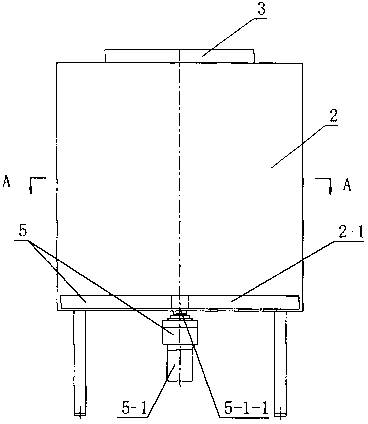
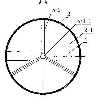
[0013] Such as figure 1 with figure 2 As shown, a silo includes a cylindrical silo body 2 arranged on a frame 1 and also includes a sweeping device 5 . The upper part of the warehouse body 2 has a feed inlet 3, and the bottom panel 2-1 of the warehouse body 2 has a discharge outlet 4, and the bottom panel 2-1 of the warehouse body 2 has two discharge outlets 4. The sweeping device 5 includes a motor 5-1 and a sweeping blade 5-2, the output shaft 5-1-1 of the motor 5-1 is positioned at the center position of the bottom panel 5-1 of the warehouse body 5, and the output of the motor 5-1 The shaft 5-1-1 is connected with the sweeping blade 5-2. There are three sweeping blades 5-2.
Login to View More PUM
 Abstract
The invention relates to a storage device, in particular to a bin with a material sweeping device. The bin comprises a tubular bin body (2) arranged on a rack (1). A feed port (3) is reserved in the upper part of the bin body (2). A discharge port (4) is reserved in a bottom panel (2-1) of the bin body (2). The bin also comprises the material sweeping device (5). The material sweeping device (5) comprises a motor (5-1) and material sweeping blades (5-2). An output shaft (5-1-1) of the motor (5-1) is positioned at the central position of the bottom panel (2-1) of the bin body (5), and is connected with the material sweeping blades (5-2). The bin is provided with the material sweeping device, and has power, and the material sweeping blades are driven by the motor to rotate to push materials in the bin into the discharge port, so that blocking and bridging phenomena when the materials are discharged are avoided, and the materials can be discharged smoothly, uniformly and stably.
Description
technical field [0001] The invention relates to a material storage device, in particular to a material bin with a material sweeping device. The invention belongs to the technical field of mechanical equipment manufacturing and processing. Background technique [0002] In the feed, food, biomass, chemical, building materials and pharmaceutical industries, the silo is a kind of non-powered material storage equipment that is widely used, and it can also be set above the mixer, granulator and other equipment as a batching preparation silo In use, the silo is an intermediate device in the process of material transportation and processing. The existing silo structure generally includes a cylindrical silo body arranged on the frame. There is a feed inlet on the upper part of the silo body, and a discharge port is opened on the bottom panel of the silo body. The material enters the silo body through the feed inlet. , stored in the bin body, when the material needs to be output, o...
Claims
Login to View More Application Information
Patent Timeline
 IPC IPC(8): B65D88/68
Inventor耿福生耿震华
Owner溧阳市华生机械制造有限公司