Rotary control hydraulic system and crane

A hydraulic system and control terminal technology, which is applied in cranes, mechanical equipment, fluid pressure actuators, etc., can solve the problems of main oil circuit pressure release, jitter, and pressure cannot be released in time, and achieve the effect of good buffer function

Active Publication Date: 2013-04-03
XUZHOU HEAVY MASCH CO LTD
View PDF5 Cites 19 Cited by
  • Summary
  • Abstract
  • Description
  • Claims
  • Application Information

AI Technical Summary

Problems solved by technology

[0007] First, the control oil port of the buffer valve 11 is connected to the feedback oil circuit 12. The pressure of the feedback oil circuit 12 will fluctuate with the fluctuation of the load pressure. When the fluctuation frequency is high or the amplitude is large, the buffer valve 11 cannot respond in time for buffering , will cause the system pressure to fluctuate, and the external performance is jitter;
[0008] Second, when the handle returns to the neutral position ( figure 1 When the main reversing valve is in the neutral position), the main oil circuit is blocked at the main reversing valve, and the actuators (such as figure 1 The middle rotary motor) cannot stop in time, but continues to compress the working chamber and pipeline of the rotary motor under the action of inertia, that is, the single-side main oil circuit under high pressure will continue to be high pressure, and the oil pressure of the feedback oil circuit 12 will be relatively high accordingly. High, the spring chamber of the buffer valve 11 is still under high pressure and closed, unable to release the pressure of the main oil circuit, which will cause a high-pressure cycle between the two main oil circuits until the movement of the actuator stops, causing jitter;
[0009] Third, when stopping, the damping 15 will also cause the pressure in the spring chamber of the buffer valve 11 to not be released in time, resulting in jitter

Method used


Image

  • Rotary control hydraulic system and crane
  • Rotary control hydraulic system and crane
  • Rotary control hydraulic system and crane

Examples


Embodiment Construction

[0029] The core of the present invention is to provide a slewing control hydraulic system and a crane, the hydraulic system makes the slewing system more stable when starting and stopping.

[0030] In order to enable those skilled in the art to better understand the technical solutions of the present invention, the present invention will be further described in detail below in conjunction with the accompanying drawings and specific embodiments.

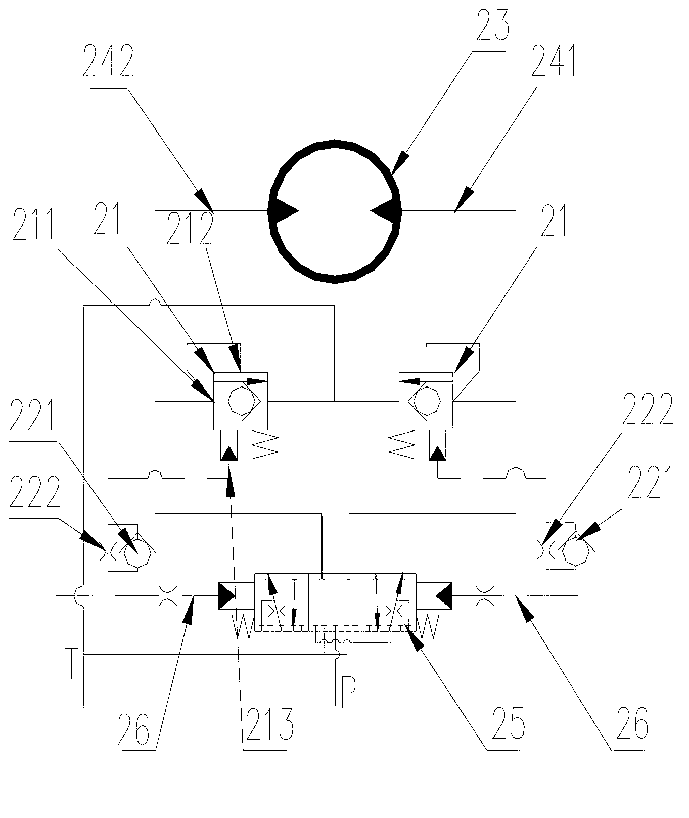
[0031] Please refer to figure 2 , figure 2 It is a principle diagram of a specific embodiment of the slewing control hydraulic system provided by the present invention.

[0032] The swing control hydraulic system in this embodiment includes a pilot oil circuit 26 and a hydraulically controlled main reversing valve 25 that controls the flow direction and on-off of the main oil circuit through the pilot oil circuit 26 . Such as figure 2 As mentioned above, the spool of the hydraulically controlled main reversing valve 25 moves lef...


PUM


Abstract

The invention discloses a rotary control hydraulic system and a crane. The rotary control hydraulic system disclosed comprises a pilot oil passage, a hydraulic control main reversing valve for controlling the flow direction and on/off of a main oil passage by the pilot oil passage, and a cushion valve, wherein the cushion valve is provided with a first working oil port, a second working oil port and a control oil port for controlling the on/off of the first and the second working oil ports. When the first and the second working oil ports are communicated with each other, the high pressure segment of the main oil passage is communicated with an oil return passage through the cushion valve, the control oil port of the cushion valve is communicated with the pilot oil passage, a damp is arranged on a passage from the control oil port to the pilot oil passage, and the control oil port of the cushion valve is communicated with the pilot oil passage, and the pilot oil source is a low-pressure and stable oil source which is independent from a load pressure. Compared with the background art that the cushion valve is communicated with the feedback oil passage having larger fluctuation, the cushion valve, provided by the invention, is not affected by load fluctuation and can give a timely response for cushioning, so that the rotary system keeps more stable during start-up and stop.

Description

technical field [0001] The invention relates to the technical field of engineering machinery, in particular to a hydraulic system for slewing control and a crane. Background technique [0002] The slewing control system of the truck crane is mainly to ensure that it can be kept stable, reliable and without impact when starting and stopping, and this function is generally realized through the slewing buffer valve. [0003] Please refer to figure 1 , figure 1 It is a schematic diagram of a rotary control hydraulic system in the prior art. [0004] figure 1 Among them, it mainly includes a quantitative pump, a proportional control valve with a three-way pressure compensator, and an independent buffer valve 11. The proportional control valve is the main reversing valve, and the buffer valve 11 is the overflow valve. A working oil port of the buffer valve 11 is connected to The oil return circuit, the other working oil port is connected to the first main oil circuit 13 at hig...

Claims


Application Information

Patent Timeline
Patent Type & Authority Applications(China)
IPC IPC(8): B66C23/86B66C13/20F15B11/02F15B13/04
Inventor 王守伟王清送胡小冬
Owner XUZHOU HEAVY MASCH CO LTD
Why Eureka
Try Eureka