A Potential Imaging Method for Detecting the Integrity of High Polymer Cutoff Wall

A technology of anti-seepage wall and integrity, which is applied in the direction of basic structure test, construction, and basic structure engineering, etc. It can solve the problems such as the grouting effect of high polymer anti-seepage wall that has not been seen, and achieve intuitive and clear detection results. The effect of high efficiency and low cost

Inactive Publication Date: 2015-09-09
SHANGHAI JIAOTONG UNIV
View PDF9 Cites 2 Cited by
  • Summary
  • Abstract
  • Description
  • Claims
  • Application Information

AI Technical Summary

Problems solved by technology

There is no report on the research results on the detection of the grouting effect of the polymer cut-off wall

Method used


Image

  • A Potential Imaging Method for Detecting the Integrity of High Polymer Cutoff Wall
  • A Potential Imaging Method for Detecting the Integrity of High Polymer Cutoff Wall
  • A Potential Imaging Method for Detecting the Integrity of High Polymer Cutoff Wall

Examples


Embodiment 1

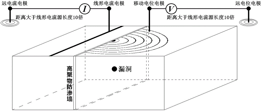
[0036] A potential mapping method for detecting the integrity of polymer cut-off walls, which is based on the physical property of high polymers to be electrically insulating, by emitting a current underground on one side of the cut-off wall and measuring the surface on the other side The potential (or potential difference) distribution of the potential (or potential difference), and the integrity of the underground cut-off wall can be obtained from the analysis of the potential distribution characteristics. It can be mainly used (but not limited to) to detect the integrity of polymer underground cut-off walls along structures such as reservoir dams, river dams and expressways.

[0037] Such as figure 1 As shown, the above method is applied to the detection of the integrity of the general underground cut-off wall, including the following steps:

[0038] Step 1: Set up a current emission system on one side of the anti-seepage wall. The current emission system includes a remote...

Embodiment 2

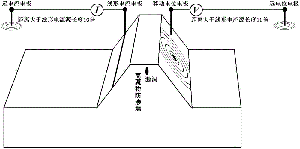
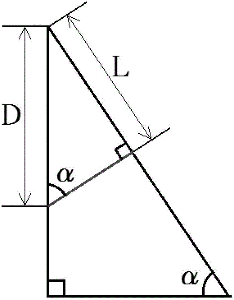
[0049] Such as figure 2 Shown is a schematic diagram of the principle of applying the potential imaging method for detecting the integrity of polymer cut-off walls to the detection of cut-off walls in embankments. This embodiment is basically the same as Embodiment 1. Such as image 3 As shown, in this embodiment, when the anti-seepage wall has a hole, the buried depth of the hole is calculated by the following formula:

[0050] Burial depth D = the oblique distance L / sin(α) from the extreme point of the equipotential line on the potential distribution diagram to the outcrop of the anti-seepage wall

[0051] sin(α) is the sine of the embankment slope angle α.

Embodiment 3

[0053] Such as Figure 5 As shown, in the potential mapping method for detecting the integrity of the polymer cut-off wall in this embodiment, the linear current source electrode is a plurality of electrodes connected by wires buried parallel to the axis of the cut-off wall, and the buried depth is about 0.3 meters. With embodiment 1.


PUM


Abstract

The invention relates to a potential imaging method for detection of integrity of a polymer impervious wall. The method comprises the following steps of: setting a current transmitting system on one side of the impervious wall, wherein the current transmitting system comprises a remote current electrode, a linear current source electrode and a current transmitting device, the linear current source electrode is arranged in parallel to the axial line of the impervious wall, and the current transmitting device is connected between the linear current source electrode and the remote current electrode; taking the other side of the impervious wall as a potential measurement plane, and setting a potential measuring system on the potential measurement plane; transmitting alternating direct current through the current transmitting system to the underground of one side of the impervious wall, and measuring potential distribution of every point on the other side of the impervious wall through the potential measuring system at certain special intervals; drawing potential distribution diagrams of every point according to the measured data, including an equipotential line chart or an equipotential gradient line chart; and judging the integrity of the impervious wall according to potential levels and potential distribution patterns in the potential distribution diagrams. Compared with the prior art, the potential imaging method has the advantages of high detection efficiency, low cost and convenient operation.

Description

technical field [0001] The invention relates to a geotechnical engineering detection method, in particular to a potential mapping method for detecting the integrity of high polymer anti-seepage walls. Background technique [0002] The non-aqueous reactive polymer grouting material represented by two-component foamed polyurethane has the characteristics of environmental protection, safety, controllable reaction speed, high expansion rate, waterproof and impervious, and good durability. High polymer grouting material with excellent comprehensive performance. The polymer grouting technology based on this material, by injecting two-component polymer materials into the foundation, utilizes the characteristics of rapid expansion and solidification of the volume of polymer materials after chemical reactions, to achieve reinforcement of the foundation, filling and detachment. Empty, lift the floor or achieve the purpose of plugging and anti-seepage. In recent years, the research a...

Claims


Application Information

Patent Timeline
Patent Type & Authority Patents(China)
IPC IPC(8): E02D33/00
Inventor 冯少孔车爱兰张国新朱新民
Owner SHANGHAI JIAOTONG UNIV
Why Eureka
Try Eureka