Performance detection module for automobile electronic water valve

A technology for automotive electronics and detection molds, applied in the direction of mechanical valve testing, etc., can solve problems such as errors in results, inability to reuse water, and inability to display test results, and achieve the effect of improving test efficiency and reducing test costs.

Inactive Publication Date: 2022-07-12
苏州睿力泰克自动化技术有限公司
View PDF0 Cites 0 Cited by
  • Summary
  • Abstract
  • Description
  • Claims
  • Application Information

AI Technical Summary

Problems solved by technology

[0003] Existing performance testing modules for automotive electronic water valves require a large amount of water when testing water valves, and cannot reuse the water after these tests, and cannot visually display the test results It is shown that there are often errors in the results that need to be calculated

Method used


Image

  • Performance detection module for automobile electronic water valve
  • Performance detection module for automobile electronic water valve
  • Performance detection module for automobile electronic water valve

Examples


Embodiment 1

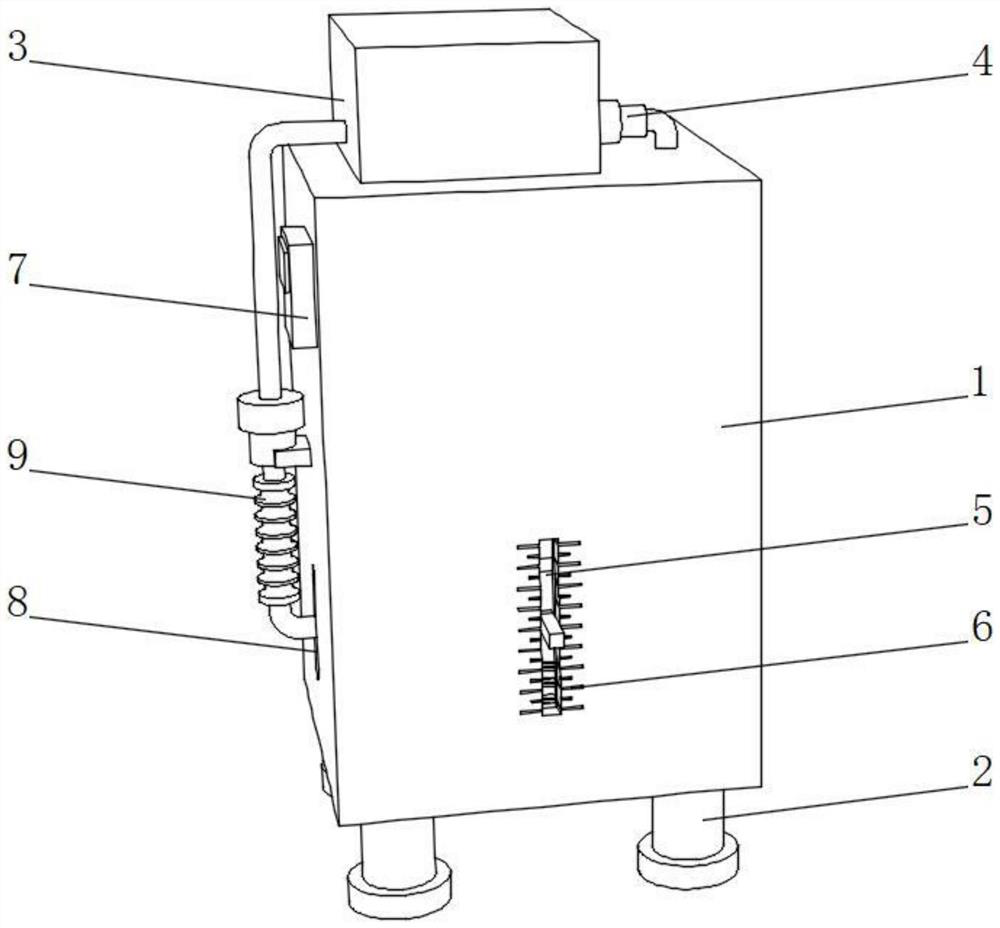
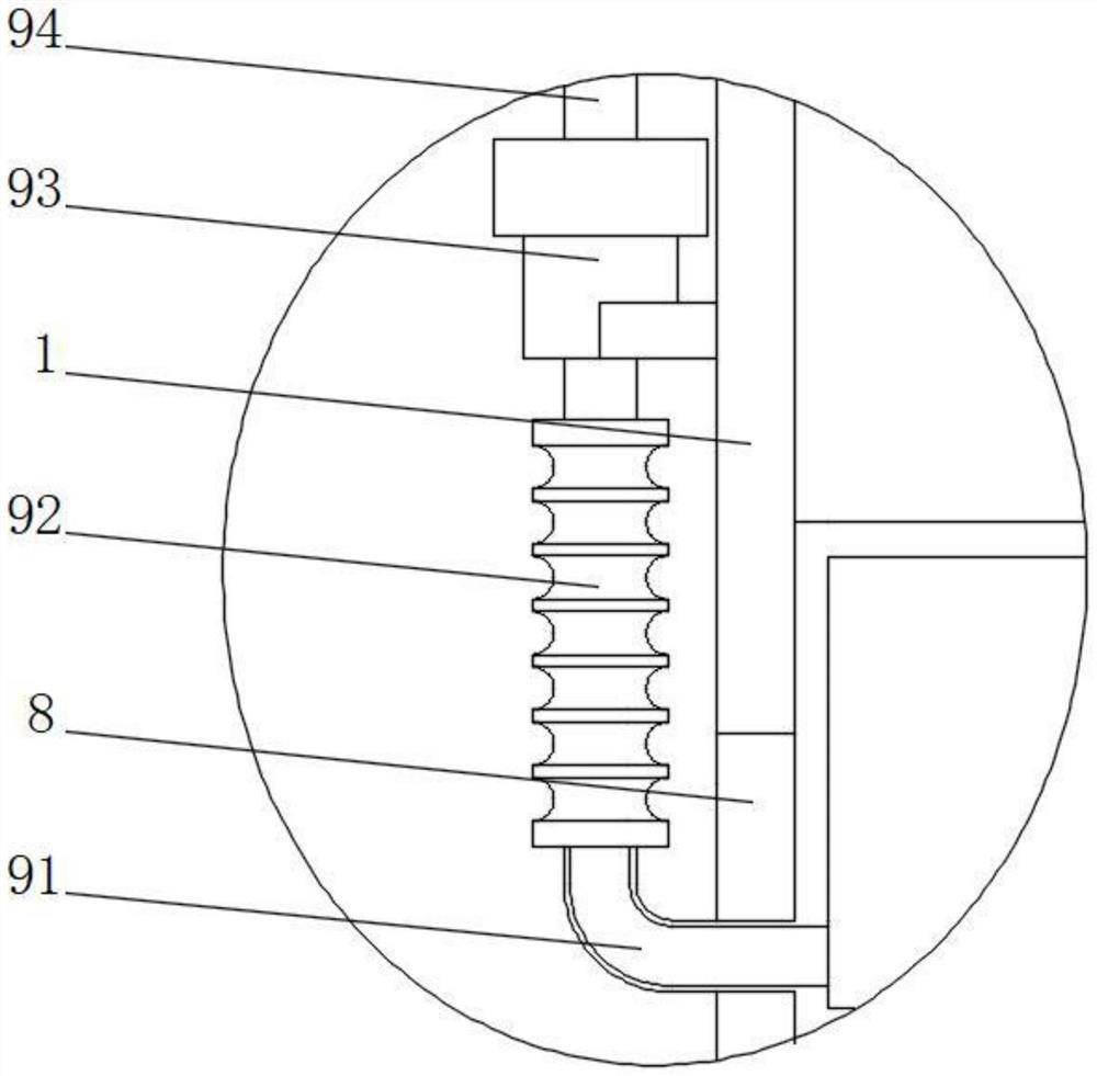
[0024] see figure 1 , figure 2 and image 3 , A performance detection module for an automobile electronic water valve proposed by the present invention includes a box body 1, a support leg 2 is fixedly connected to the bottom of the box body 1, a water tank 3 is fixedly connected to the top side of the box body 1, and the water tank 3 One side of the first connecting pipe is connected with a first connecting pipe, one end of the first connecting pipe penetrates the top wall of the box 1 and extends to the inside, the surface of the first connecting pipe is fixedly connected with the first water pump 4, and the front of the box 1 is on the back. Through holes 5 are opened on the surface of the box body 1 and scale lines 6 are opened on both sides of the through hole 5. One side of the box body 1 is fixedly connected with the controller 7, and one side of the box body 1 is provided with a movable hole 8. , one side of the movable hole 8 is provided with a circulation mechanis...

Embodiment 2

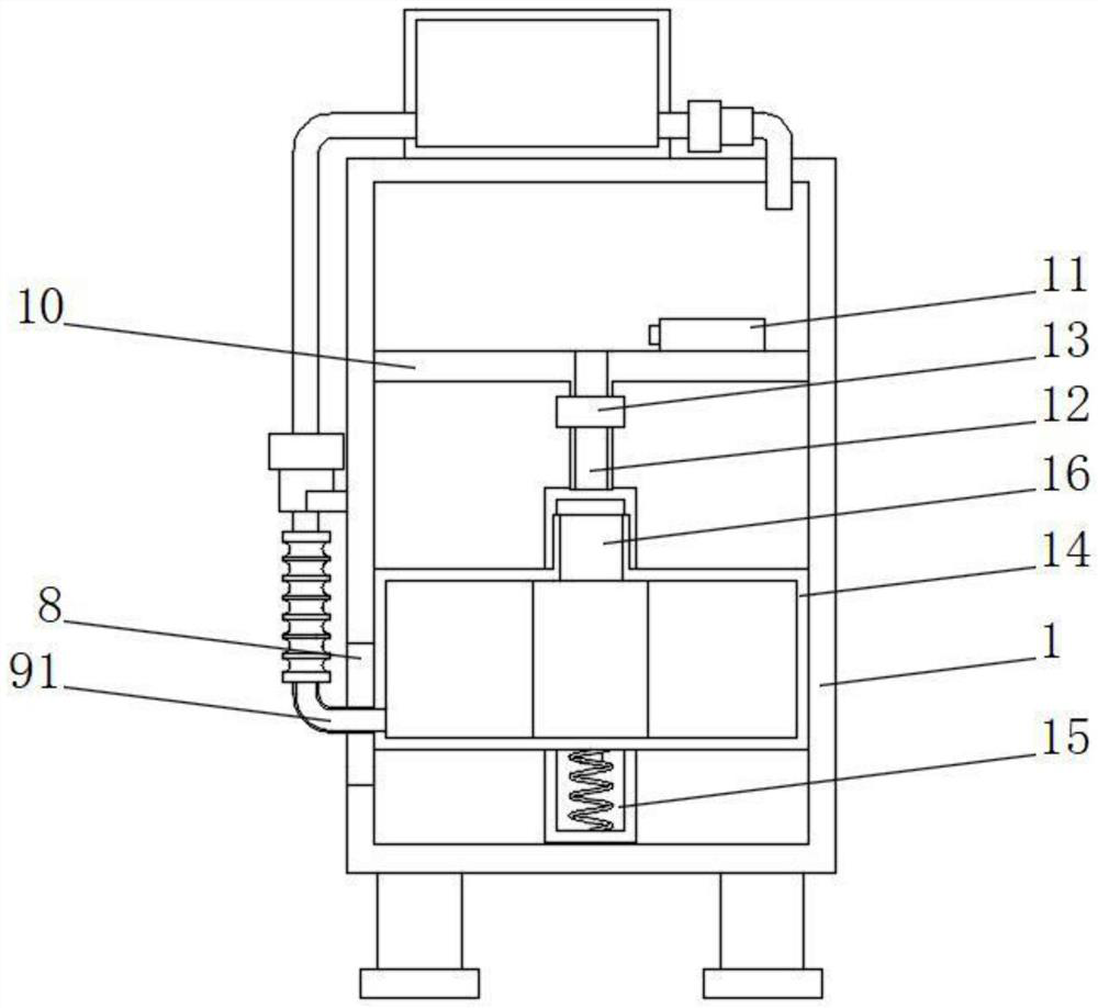
[0031] see image 3 and Figure 4 , as an improvement of the above scheme, the inside of the box body 1 is slidably connected with a collection box 14, the top of the collection box 14 is fixedly connected with a receiving pipe 16, and the second connecting pipe 91 passes through the movable hole 8 and is fixed to one side of the collection box 14 A sliding mechanism 15 is arranged between the surface of the collection box 14 and the inner wall of the box body 1. In the present invention, the collection box 14, the sliding mechanism 15, the sliding block 151, the sliding rail 152, the spring 153, the indicator rod 154, the receiving pipe 16. The amount of water in the collection box 14 can be visually displayed through the compression degree of the spring 153, and the amount of water in the collection box 14 can be displayed through the indicator rod 154 and the scale line 6, so that the test results are more intuitive and clear, Improve test efficiency.

[0032] As an impro...


PUM


Abstract

The invention discloses an automobile electronic water valve performance detection module which comprises a box body, the bottom of the box body is fixedly connected with supporting legs, one side of the top of the box body is fixedly connected with a water tank, one side of the water tank is in pipe connection with a first connecting pipe, and one end of the first connecting pipe penetrates through the top wall of the box body and extends into the box body. A first water pump is fixedly connected to the surface of the first connecting pipe, through holes are formed in the front face and the back face of the box body, scale marks are formed in the positions, located on the two sides of the through holes, of the surface of the box body, a controller is fixedly connected to one side of the box body, a movable hole is formed in one side of the box body, and a circulating mechanism is arranged on one side of the movable hole and comprises a second connecting pipe; the second connecting pipe is located in the movable hole, the top end of the second connecting pipe is fixedly connected with a corrugated pipe, the top of the corrugated pipe is fixedly connected with a second water pump, and one side of the second water pump is fixedly connected with one side of the box body.

Description

technical field [0001] The invention relates to the field of detection modules, in particular to a performance detection module for automobile electronic water valves. Background technique [0002] The electronic water valve is a shunt, confluence or flow direction switching device. The electronic water valve adopts a top-loading structure, which reduces the connecting bolts of the valve body itself under the condition of high pressure and large diameter, which enhances the reliability of the valve and can overcome the system's own weight. Due to the influence of normal work, electronic water valves are widely used in coal chemical, petrochemical, rubber, paper, pharmaceutical and other pipelines as media shunting and confluence or flow direction switching devices. Automotive electronic water valves need to be tested for tightness before leaving the factory. Flow test to ensure that it can be used normally in the future, so it is necessary to use the performance detection mo...

Claims


Application Information

Patent Timeline
Patent Type & Authority Applications(China)
IPC IPC(8): G01M13/003
CPCG01M13/003
Inventor 赵文兵
Owner 苏州睿力泰克自动化技术有限公司
Why Eureka
Try Eureka