Pneumatic high pressure regulating valve

A pneumatic high-pressure, regulating valve technology, applied in the direction of valve lift, valve details, valve devices, etc., can solve the problems of small output force, low operating pressure difference, and short service life of pneumatic actuators, so as to achieve stable flow and reduce flushing speed Effect

Active Publication Date: 2013-04-03
MAXCO IND TECH (SHANGHAI) CO LTD
View PDF7 Cites 22 Cited by
  • Summary
  • Abstract
  • Description
  • Claims
  • Application Information

AI Technical Summary

Problems solved by technology

[0006] The technical problem to be solved by the present invention is to solve the vibration, noise, leakage, short service life and pneumatic actuation caused by partial wear, wear, scouring, scratches and other phenomena of the inner parts of the ordinary pneumatic high-pressure regulating valve. The defects such as small output force of the mechanism and low operating pressure difference have been improved, and a pneumatic high-pressure regulating valve with a special structure has been designed.

Method used


Image

  • Pneumatic high pressure regulating valve
  • Pneumatic high pressure regulating valve
  • Pneumatic high pressure regulating valve

Examples


Embodiment 1

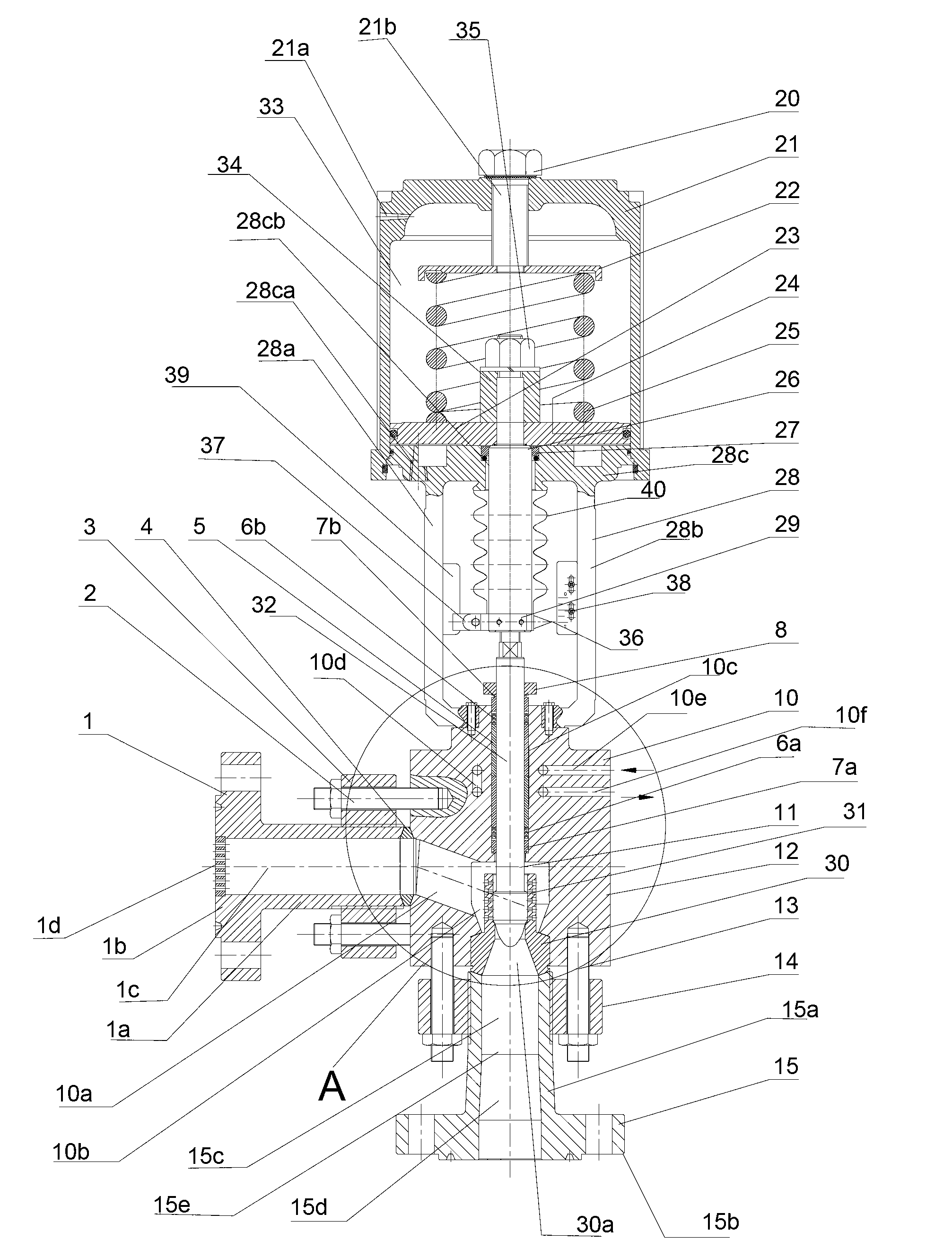
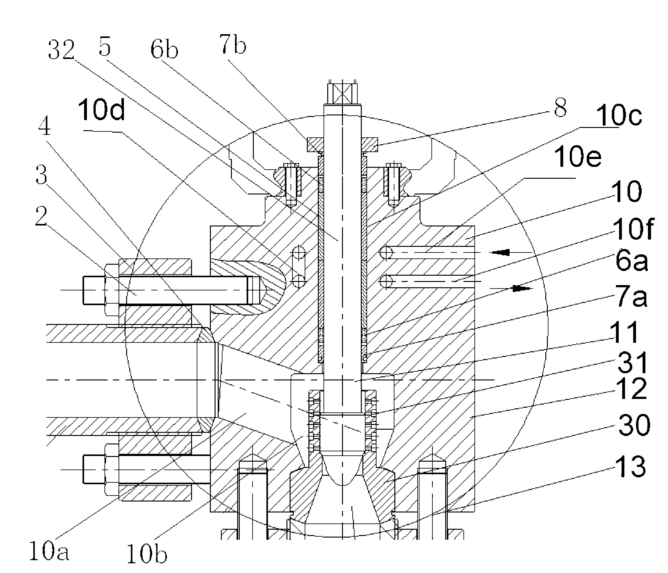
[0065] see figure 1 and figure 2 , an air-opening pneumatic high-pressure regulating valve given in the figure includes an air-opening spring-cylinder actuator and a valve part arranged below the air-opening spring-cylinder actuator.

[0066] The valve part includes a valve body 10, and the valve cover on the valve body 10 and the valve body are integrally forged by stainless steel, so as to avoid leakage points generated by the flange connection. The valve body 10 is provided with an inlet flow channel 10a, an outlet flow channel 10b and a stem hole 10c which communicate with each other. The inlet flow channel 10a and the outlet flow channel 10b are streamlined, and the flow channels are smooth without dead zones. The outlet channel 10b is coaxially arranged with the valve stem hole 10c, and the angle between the central axis of the inlet channel 10a and the center axis of the outlet channel 10b is 120°, which can make the medium flow smoothly and at the same time generate ...

Embodiment 2

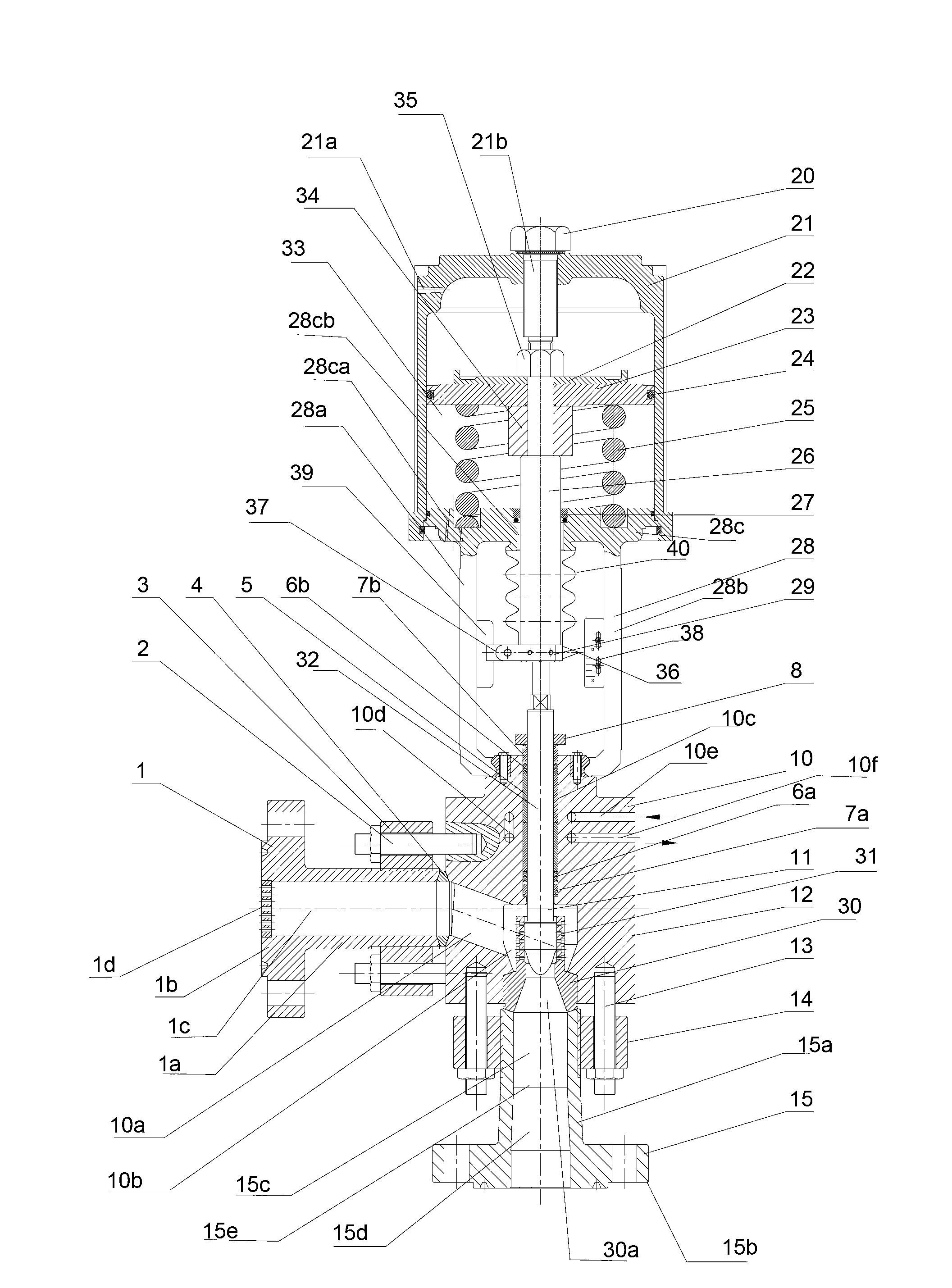
[0084] see image 3 , the pneumatic high-pressure regulating valve of this embodiment shown in the figure is an air-closing pneumatic high-pressure regulating valve, including an air-closing spring-cylinder actuator and a valve part arranged below the air-opening spring-cylinder actuator . Wherein the valve part is the same as that of Embodiment 1.

[0085] The air-to-close spring cylinder actuator has a different structure from the air-to-open spring cylinder actuator in Embodiment 1. The air-to-close spring cylinder actuator includes a bracket 28, and the bracket 28 has two arms 28a, 28b. , the lower ends of the two support arms 28a, 28b are fixed on the valve body 10 by bolts, and a cylinder base flange 28c is integrally connected to the upper ends of the two support arms 28a, 28b, and a gas inlet flange 28c is provided on the cylinder base flange 28c. hole 28ca and a central push rod hole 28cb.

[0086] The cylinder body 21 in the air-open spring cylinder actuator is a ...


PUM


Abstract

The invention discloses a pneumatic high pressure regulating valve. The pneumatic high pressure regulating valve comprises an executing mechanism and a valve part which is arranged under the executing mechanism, wherein the valve part comprises a valve body; an inlet runner and an outlet runner are arranged in the valve body; and an angle formed between the inlet runner and the outlet runner is 120 degrees. The pneumatic high pressure regulating valve disclosed by the invention has the advantages as follows: as the plurality of special structural designs are adopted, applicable pressure difference of the valve is very high and cavitation phenomenon is completely eliminated; sensitive action and high response speed are obtained and the pneumatic high pressure regulating valve can be freely closed and opened and can be tightly closed when meeting very high fluid pressure difference; a side flange and a valve cage of the specially designed valve body can be also used for guiding fluid, buffering fluid pressure and protecting a valve core against being damaged by fluid ablation, flash evaporation and cavitation; meanwhile, noises can be also reduced; simple and rapid maintenance and low cost are also obtained; the service life is obviously prolonged; and the pneumatic high pressure regulating valve is especially suitable for automatically controlling high temperature and high pressure mediums with high pressure differences and is safe and reliable in use. The pneumatic high pressure regulating valve disclosed by the invention is especially incomparable with other valves in advantages when being used for places with high pressure urea and other easily crystallized mediums.

Description

technical field [0001] The invention relates to a pneumatic high-pressure regulating valve. Background technique [0002] Pneumatic high-pressure regulating valves are mainly used in automatic control systems for high-pressure and high-pressure differential conditions in petroleum, chemical, fertilizer, power generation and other industries. The process conditions are relatively harsh, and the reliability and safety requirements for regulating valves are relatively high. [0003] The common type pneumatic high-pressure control valve is a 90-degree right-angle angle control valve equipped with a multi-spring pneumatic diaphragm actuator. Due to the low compressive strength of the rubber diaphragm, the air source pressure is low and the output force is relatively small. Furthermore, because the flow path of the valve body is in the shape of a 90-degree right angle, the impact force of the high-pressure fluid is very large. The valve cage is equipped with a common structure, an...

Claims


Application Information

Patent Timeline
Patent Type & Authority Applications(China)
IPC IPC(8): F16K1/00F16K1/32F16K41/02F16K47/08F16K31/122F16K27/02F16K37/00
Inventor 汪广庆
Owner MAXCO IND TECH (SHANGHAI) CO LTD
Why Eureka
Try Eureka