An equal-flow air distributor for supplying air to high-pressure disc gas bearings

An air flow distributor and gas bearing technology, which is applied in the direction of pipe components, branch pipelines, mechanical equipment, etc., can solve the problem that the high-pressure disc gas bearing gas supply system cannot provide, can not achieve split flow and export it in an equal amount, and the final gas problems such as low pressure, to achieve the effect of satisfying structural strength design, novel structure and small pressure loss

Active Publication Date: 2021-01-05
WUHAN UNIV OF SCI & TECH
View PDF17 Cites 0 Cited by
  • Summary
  • Abstract
  • Description
  • Claims
  • Application Information

AI Technical Summary

Problems solved by technology

[0005] Application No. 201611065628.5, the invention patent "a graded gas low-nitrogen burner", mentioned that the distributor is mainly used to provide a flow path for gas and air, so as to realize the efficient mixing of gas staged injection and three-layer combustion-supporting air, so as to Complete combustion, the pressure of the final gas is low, which cannot meet the requirements of splitting the high-pressure gas flow from the main pipeline and leading it to two or more branch pipelines in equal amounts in the high-pressure disc gas bearing gas supply system
[0006] To sum up, the existing air distributor cannot provide two or more high-pressure airflows with equal flow rate for the high-pressure disc gas bearing air supply system, and cannot meet the requirements of maintaining high-pressure airflow in the high-pressure disc air bearing air supply system. To split the flow into two or more high-pressure airflows and export them, it is urgent to develop an equal-flow airflow distributor to meet the technical requirements

Method used


Image

  • An equal-flow air distributor for supplying air to high-pressure disc gas bearings
  • An equal-flow air distributor for supplying air to high-pressure disc gas bearings
  • An equal-flow air distributor for supplying air to high-pressure disc gas bearings

Examples


Embodiment 1

[0042] The present invention will be further described below in conjunction with the accompanying drawings.

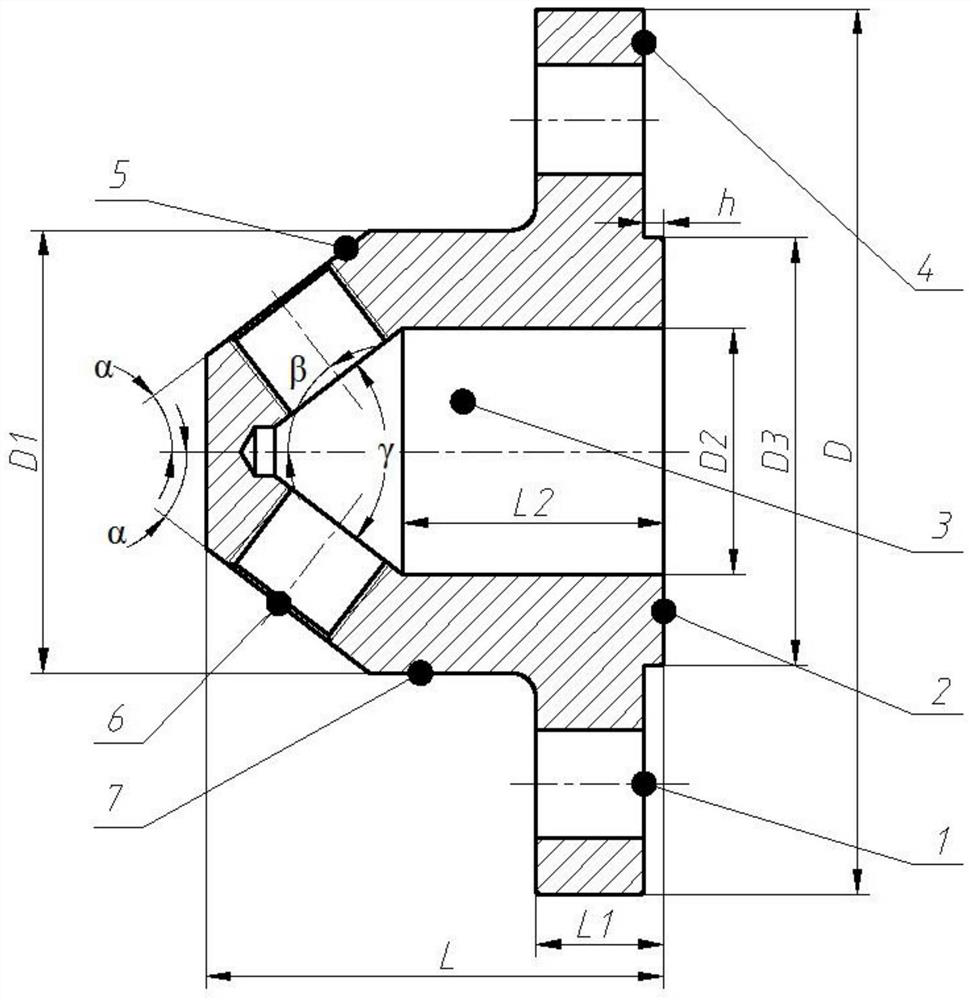
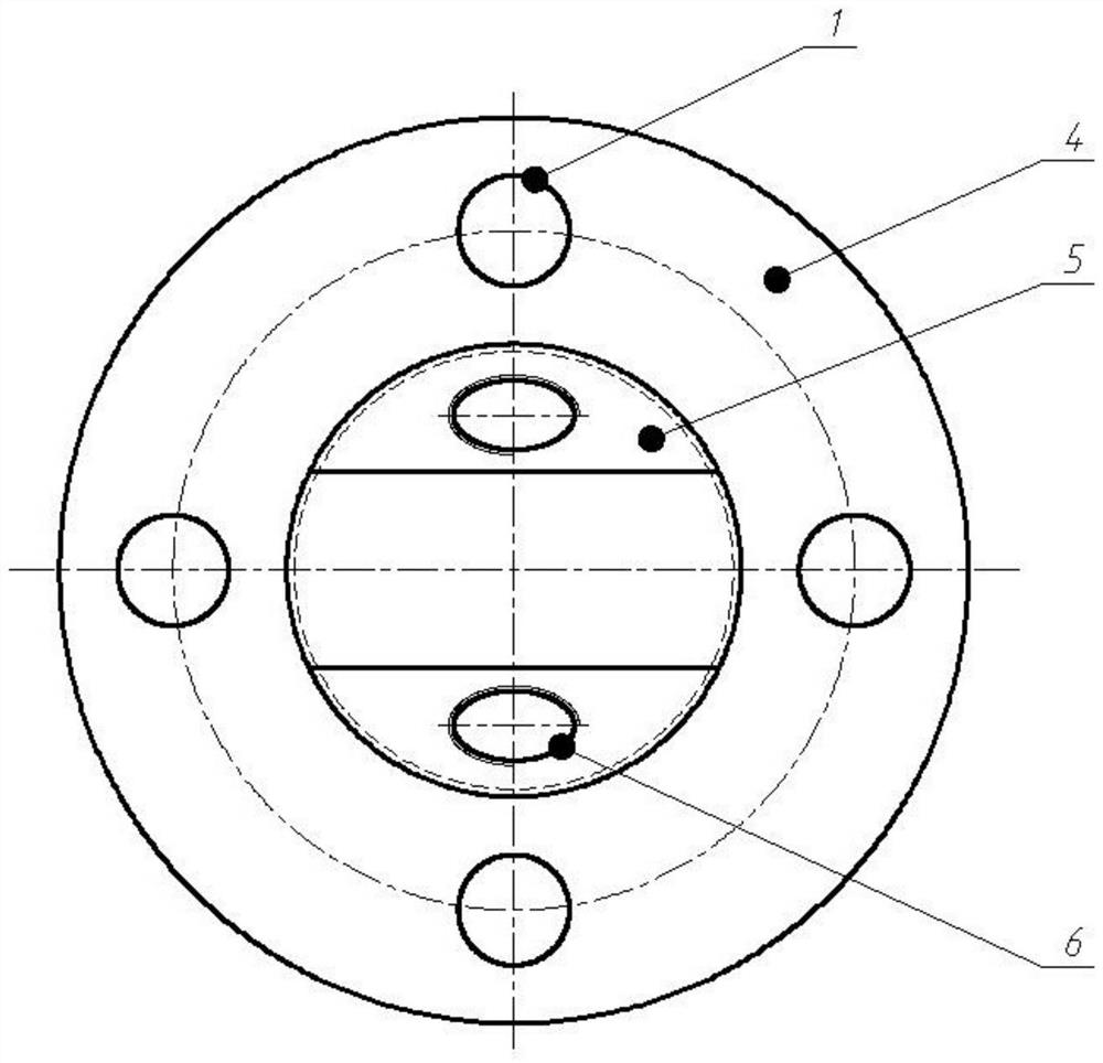
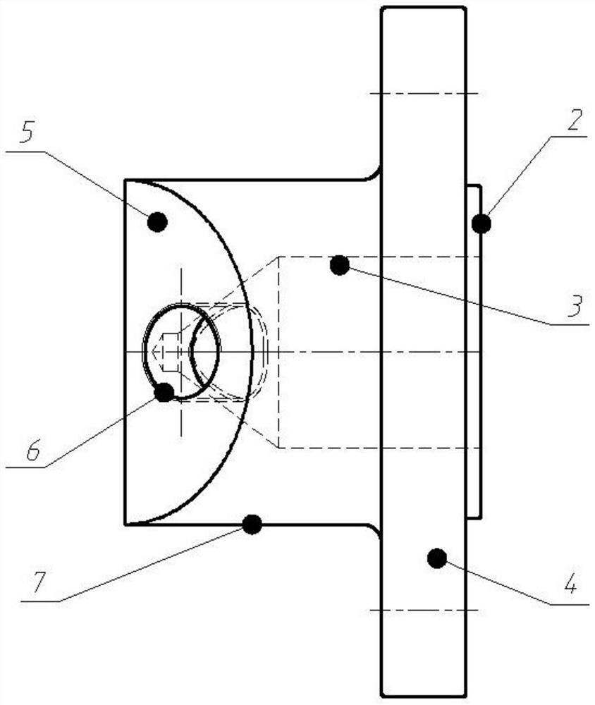
[0043] Such as Figure 1-Figure 3 As shown, there is a gas flow distributor with two branch pipes, which is used to split the flow to two working discs of a set of high-pressure disc gas bearings, which includes a centrally symmetrical cylindrical air flow cavity 7, and the cylindrical air flow The inside of the chamber 7 is provided with a centrally symmetrical cylindrical-cone transitional gas chamber 3, and the right end of the cylindrical airflow chamber 7 is provided with a connecting disc 4; the central axis of the cylindrical airflow chamber 7 is located at the same on a straight line;

[0044]The left end of the cylindrical air flow chamber 7 is milled with two slopes 5 at an angle of 37.5° with the central axis, and the slopes 5 are evenly distributed along the central axis; each slope 5 has a threaded hole 6 in the center, and the threaded hole 6 is connecte...

Embodiment 2

[0060] see Figure 9-Figure 11 , shows a gas flow distributor with four branch pipes for splitting equal flows to the four working discs of two sets of high-pressure disc gas bearings.

[0061] Except for increasing the number of branch pipelines, all the other features are the same as those in Embodiment 1.

[0062] Figure 9 Shown is a left side view of the distributor with four branch pipes, and the figure shows four symmetrical slopes 5 up and down, left and right, and the position distribution of four symmetrically arranged threaded holes on the slopes.

[0063] Figure 10 Shown is the top view of the distributor with four branch pipes, which shows the top view shape and position distribution of the four inclined planes 5 milled on the cylindrical air flow chamber 7 and the four threaded holes 6 processed .

[0064] The distributor embodiment 2 is similar to the geometric parameters of embodiment 1. Figure 11 When the air supply pressure is 0.9MPa, the outlet pressu...

Embodiment 3

[0067] see Figure 14 , Figure 15 , Figure 16 , shows an airflow distributor when the number of branch pipes is equal to 4, but the outflow angle changes, and is used to divide the flow to the four working discs of the two sets of high-pressure disc gas bearings.

[0068] The left end of the cylindrical airflow cavity 7 is milled with four slopes 5 at an angle of 45° with the central axis, and the slopes 5 are evenly distributed along the central axis; each slope 5 is provided with a threaded hole 6, and the threaded hole 6 is connected to the central axis. The angle between the central axis is 30°;

[0069] The right end of the cylindrical-cone transitional gas cavity 3 is cylindrical, and the left end of the cylindrical-conical transitional gas cavity 3 has a conical angle of 40°, and the cylindrical-conical transitional gas cavity 3 communicates with the threaded hole 6 .

[0070] All the other features are the same as in Embodiment 1.

[0071] Figure 14 Shown is th...


PUM


Abstract

The invention discloses a constant-flow airflow distributor for supplying gas to a high-pressure circular disc gas bearing. The constant-flow airflow distributor comprises a centrally-symmetric cylindrical airflow chamber body (7), wherein a centrally-symmetric cylinder-cone transitional-shaped gas chamber (3) is arranged in the cylindrical airflow chamber body (7), and a connecting circular disc(4) is arranged at the right end of the cylindrical airflow chamber body (7); the cylindrical airflow chamber body (7) and a central shaft of the cylinder-cone transitional shaped gas chamber (3) arepositioned on the same straight line; two or more inclined faces (5) which can form an included angle alpha together with the central shaft are milled at the left end of the cylindrical airflow chamber body (7) and are uniformly distributed along the central shaft; and threaded holes (6) are formed in the inclined faces, and an included angle beta is formed between each of the threaded holes (6) and the central shaft. The constant-flow airflow distributor disclosed by the invention has the advantages of being simple in structure and convenient to machine; column faces, cone faces and the inclined faces are geometric surfaces which are commonly seen in machining, are easily machined and assembled, and are low in cost; and therefore, airflow with uniform and constant flow can be provided formultiple working circular discs of the high-pressure circular disc gas bearing.

Description

technical field [0001] The invention relates to an air flow distribution device in a static pressure gas bearing air supply system under high air supply pressure, in particular to an equal-flow air flow distributor for supplying air to a high-pressure disc air bearing. Background technique [0002] The invention patent with the application number of 201710051054.4 "a cylindrically symmetrical inner circumferential jet flow stabilizing chamber for supplying gas to the high-pressure disc gas bearing" introduces the gas into the upper stabilizing chamber and the cavity symmetrically arranged on both sides of the working disc. An inner circumferential jet is formed inside the lower plenum cavity, thereby forming a column-symmetrical flow field; supplemented by a reasonable plenum size design, the inlet air velocity on the inlet section of the gas supply hole of the high-pressure disc gas bearing is uniform. However, this design needs to ensure that the intake volumes of the uppe...

Claims


Application Information

Patent Timeline
Patent Type & Authority Patents(China)
IPC IPC(8): F16L41/03F16L55/02
CPCF16L41/03F16L55/02
Inventor 郭良斌余振东张雄威
Owner WUHAN UNIV OF SCI & TECH
Why Eureka
Try Eureka