Non-contact throttle position sensor

A throttle position, non-contact technology, which is applied in the direction of transmission of sensing components, instruments, measuring devices, etc. using electric/magnetic devices, can solve problems such as output signal lag, brush or ceramic substrate wear, sensor failure, etc. Achieve the effect of improving output accuracy, improving service life and wide application range

Inactive Publication Date: 2013-04-03
LIANCHUANG AUTOMOBILE ELECTRONICS
View PDF5 Cites 6 Cited by
  • Summary
  • Abstract
  • Description
  • Claims
  • Application Information

AI Technical Summary

Problems solved by technology

Existing throttle position sensors are generally resistive, and the output signal is generated by the rotation of the brush on the ceramic substrate. Since the brush and the ceramic substrate are in contact, long-term friction will cause the brush to Or the ceramic substrate is worn out, making the sensor useless
In addition, the operating temperature of the throttle position sensor is relatively high, and at high temperatures, the electrical signal output by the sensor will be offset, thereby affecting the output accuracy of the throttle position sensor
Moreover, the tightness of the fit between the rotor of the sensor and the throttle shaft will affect the output signal of the sensor, and if the fit is too loose, the output signal will lag

Method used


Image

  • Non-contact throttle position sensor
  • Non-contact throttle position sensor
  • Non-contact throttle position sensor

Examples


Embodiment Construction

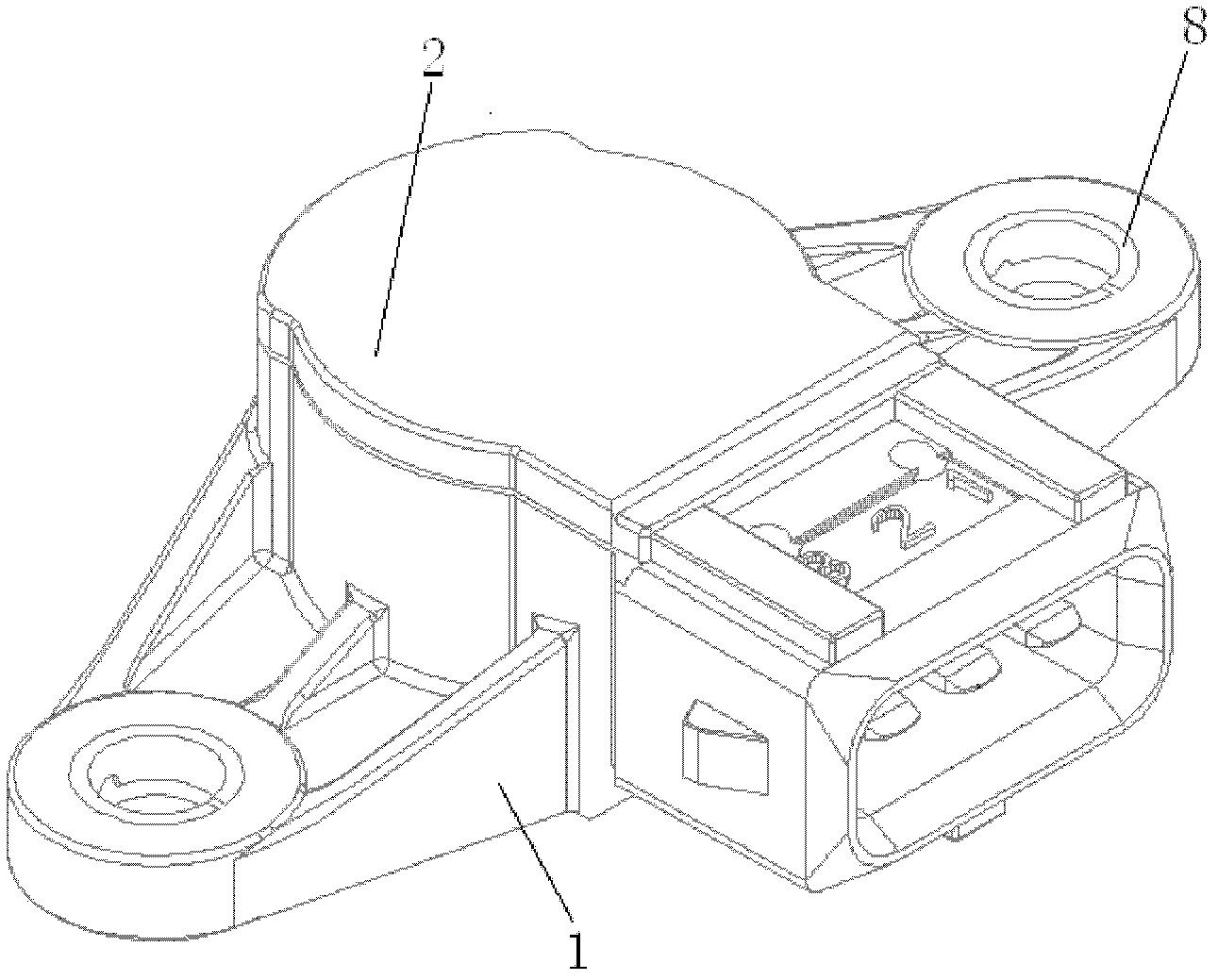
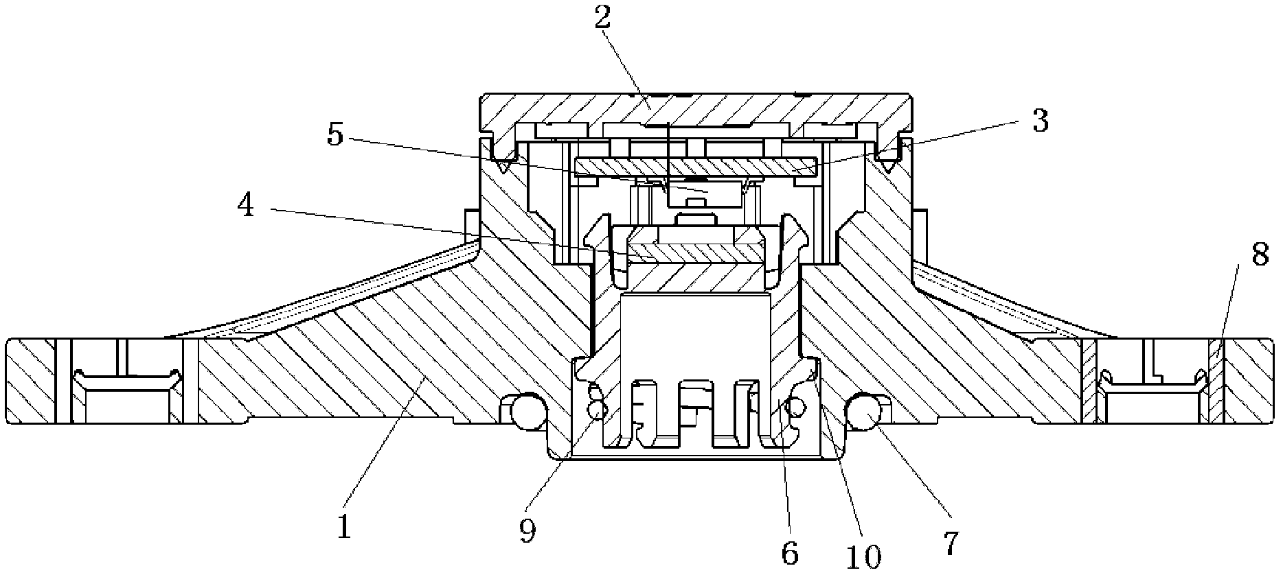
[0018] The non-contact throttle position sensor of the present invention, as figure 1 It is mounted on the throttle body as shown. The sensor includes a housing 1, a cover plate 2, a circuit board 3, a Hall element 5, a magnetic element and a rotor 6, wherein the circuit board 3, the Hall element 5, the magnetic element and the rotor 6 are located in the housing 1, such as image 3 shown. The rotor 6 is closely connected with the throttle shaft, the magnetic element is fixedly installed on the rotor 6, the circuit board 3 is installed on the housing 1, and is fixedly connected with the Hall element 5, and the Hall element 5 and There is a gap between the magnetic elements. The magnetic element is a magnet 4 .

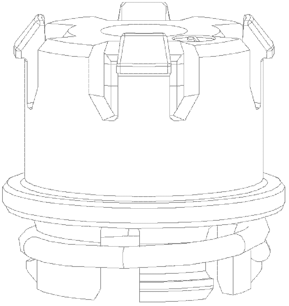
[0019] Such as figure 2 with image 3 As shown, the lower end of the rotor 6 is tightly connected to the throttle shaft through the circlip 9, so that the cooperation between the rotor 6 and the throttle shaft is tighter, thereby reducing the hysteresis error meas...


PUM


Abstract

The invention discloses a non-contact throttle position sensor which is mounted on a throttle body. The sensor comprises a shell, a cover board, a circuit board, a hall element, a magnetic element and a rotor, wherein the circuit board, the hall element, the magnetic element and the rotor are arranged in the shell, the rotor is tightly connected with a shaft of the throttle by a snap spring, the magnetic element is fixedly mounted on the rotor, the circuit board is installed on the shell and is fixedly connected with the hall element, a gap is formed between the hall element and the magnetic element, and the upper end of the rotor is provided with a plurality of buckles which can be buckled on a flange of the inner wall of the shell. According to the invention, the wearing problem caused by long-term running of the conventional throttle position sensor is effectively solved, the service life of the sensor is prolonged, the output precision of the sensor is higher, the stability of the sensor in a high-temperature environment is higher, and thus the application scope of the sensor is wider.

Description

technical field [0001] The invention belongs to a throttle body of an automobile fuel injection system, in particular to a non-contact throttle position sensor. Background technique [0002] The throttle body is a component in the automotive fuel injection system that controls the intake air volume of the engine, and the throttle position sensor provides the angle signal of the throttle body for the engine management system. Existing throttle position sensors are generally resistive, and the output signal is generated by the rotation of the brush on the ceramic substrate. Since the brush and the ceramic substrate are in contact, long-term friction will cause the brush to Or the ceramic substrate is worn out, making the sensor useless. In addition, the operating temperature of the throttle position sensor is high, and the electrical signal output by the sensor will be offset at high temperature, thereby affecting the output accuracy of the throttle position sensor. Moreover...

Claims


Application Information

Patent Timeline
Patent Type & Authority Applications(China)
IPC IPC(8): G01D5/14G01D3/036G01D11/16
Inventor 黄波韩本忠钱杰焦兴军汪晓敏
Owner LIANCHUANG AUTOMOBILE ELECTRONICS
Why Eureka
Try Eureka