Method for adopting bend test to test tensile elasticity modulus of material

A technique of tensile elastic modulus and bending test, which is applied in the direction of testing the strength of materials by applying a stable bending force, and can solve the problems of complex elastic modulus calculation formula, inconvenient use, and heavy testing workload

Inactive Publication Date: 2013-04-03
SOUTHWEST JIAOTONG UNIV
View PDF5 Cites 15 Cited by
  • Summary
  • Abstract
  • Description
  • Claims
  • Application Information

AI Technical Summary

Problems solved by technology

However, this method has the following shortcomings: first, the displacement of the section where the measuring point is located needs to be tested in the experiment, and the test workload is relatively large; second, the bending moment on the cross section at different positions needs to be calculated; third, The formula for calculating the

Method used


Image

  • Method for adopting bend test to test tensile elasticity modulus of material
  • Method for adopting bend test to test tensile elasticity modulus of material
  • Method for adopting bend test to test tensile elasticity modulus of material

Examples


Embodiment 1 4

[0028] Embodiment 1 four-point bending test measures tensile modulus of elasticity

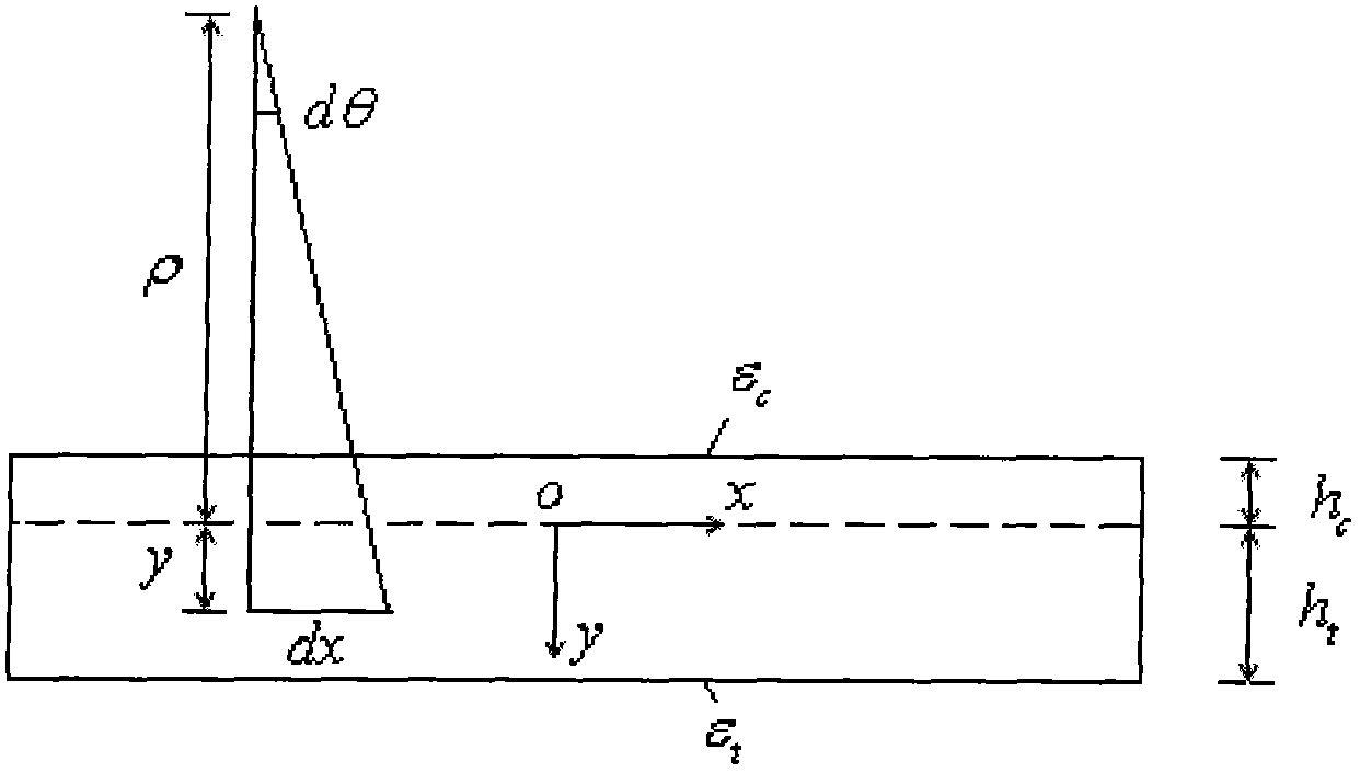
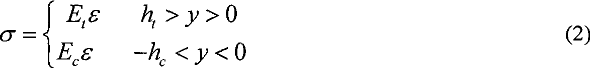
[0029] The material is processed into a rectangular parallelepiped sample, and the size of the rectangular parallelepiped meets the requirements of a slender beam, that is, the width of the sample is smaller than the height, and the ratio of the fulcrum span to the height is not less than 5. Pure bending loading is achieved using a four-point bending method. The two supporting points are arranged horizontally, and they are equidistant from the geometric center of the beam. The two loading points are also arranged horizontally, and the distance from them to the geometric center of the beam is equal, then the bending moment on any cross-section of the sample between the two loading points is a constant value, that is, the beam between the two loading points is a purely curved beam. The linear strain value of the upper and lower surfaces of the pure bending section during the loading process ca...

Embodiment 2 3

[0030] Embodiment 2 Three-point bending test measures tensile modulus of elasticity

[0031] The material is processed into a rectangular parallelepiped sample, and the size of the rectangular parallelepiped meets the requirements of a slender beam, that is, the width of the sample is smaller than the height, and the ratio of the fulcrum span to the height is not less than 5. The three-point bending method is used to achieve transverse bending loading. Assume that the two fulcrums are arranged horizontally, and their distances from the geometric center of the beam are equal. The geometric center of the imposed load spans the beam and is perpendicular to the horizontal axis of the beam. Choose a cross-section in the bending section of the beam, and arrange measuring points on the upper and lower edges of the cross-section to test the linear strain in the horizontal direction. Load the sample, the load increases gradually from 0, record the load P, and the line strain ε at the...


PUM


Abstract

The invention discloses a method for adopting a bend test to test the tensile elasticity modulus of a material. A compressive elasticity modulus Ec of a material is supposed to be known, and the pure bending or transverse bending small transformation experiment is carried out in a linear elastic range of the material; axial strain values epsilon c and epsilon t of an optional position on upper and lower surfaces of the pure bending section of a sample or axial strain values epsilon c and epsilon t on the upper and lower edges of any cross section of the transverse bending section are measured in an experiment; a relation of the pressure-pulling elasticity modulus ratio and the pulling compressive strain ratio of the material is deduced through an equilibrium condition of a cross section, thereby determining the tensile elasticity modulus Et of the material according to the formulae shown in the specification. The method provided by the invention has the advantages that the theory is correct, a computing formula is concise, the parameter is easy to measure, and the tensile elasticity modulus of the material can be accurately measured.

Description

technical field [0001] The invention relates to a method for testing the tensile elastic modulus of a material, that is, a bending test is used to test the tensile elastic modulus of the material. Background technique [0002] Elastic modulus is one of the basic mechanical parameters of materials, and it is very important to accurately test the elastic modulus of materials. Many materials (such as rocks, concrete, FRP, plastics, ceramics, graphite, etc.) often exhibit significantly different elastic moduli in tension and compression. The compressive modulus of elasticity of a material is easily obtained by uniaxial compression deformation test. The best way to measure the tensile modulus of a material is of course a uniaxial tensile deformation test. In many cases, however, performing tensile deformation tests is difficult, especially for brittle materials. In May 2010, Chongqing University's master's degree thesis "Research on Different Moduli of Tension and Compression ...

Claims


Application Information

Patent Timeline
IPC IPC(8): G01N3/20
Inventor 喻勇
Owner SOUTHWEST JIAOTONG UNIV
Why Eureka
Try Eureka