Device for testing shear strength of joint of external prestressing prefabrication and assembly concrete member

A prefabricated assembly, shear strength technology, applied in the direction of using a stable shear force to test the strength of materials, can solve the problems of not easy to control the shear force, not shear loading, and low shear loading efficiency.

Inactive Publication Date: 2013-04-03
NINGBO UNIV
View PDF3 Cites 8 Cited by
  • Summary
  • Abstract
  • Description
  • Claims
  • Application Information

AI Technical Summary

Problems solved by technology

At present, the existing design method generally adopts the simply supported beam loading mode to carry out the shear strength test, and the prefabricated assembled concrete members are subjected to pressure loading near the joint. The problem with this loading mode is that there are both shear force and Bending moment, not real pure shear loading, shear loading efficiency is not high, and it is not easy to control the actual shear force

Method used


Image

  • Device for testing shear strength of joint of external prestressing prefabrication and assembly concrete member
  • Device for testing shear strength of joint of external prestressing prefabrication and assembly concrete member
  • Device for testing shear strength of joint of external prestressing prefabrication and assembly concrete member

Examples


Embodiment 1

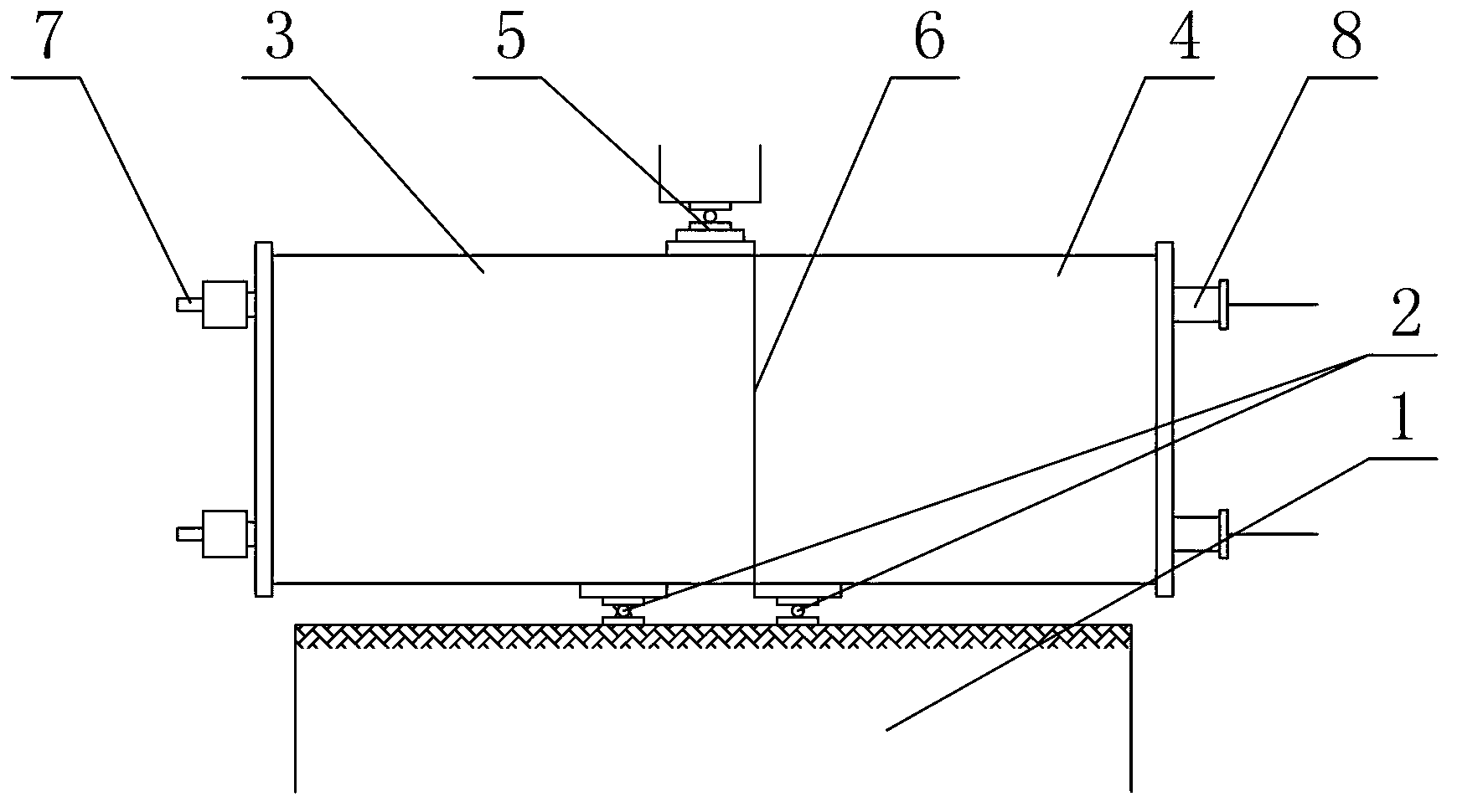
[0026] Embodiment one: if figure 2 As shown, a prefabricated assembled concrete component joint shear strength test device includes a loading base 1, a support 2 arranged on the loading base 1, a prefabricated assembled component and a hydraulic jack 5 arranged on the prefabricated assembled component. The assembled component is arranged on the support 2, and the prefabricated assembled component includes a first segment member 3 and a second segment member 4, wherein the first segment member 3 is arranged on the support 2, and the hydraulic jack 5 is arranged on the second segment On the upper end face of the segmental member 4, a vertical shearing force is applied to the prefabricated assembled member through the hydraulic jack 5; the cross section of the first segmental member 3 is L-shaped, and the cross-section of the second segmental member 4 is inverted L-shaped , the first segment member 3 and the second segment member 4 are assembled by a prestressed tensioning devic...

Embodiment 2

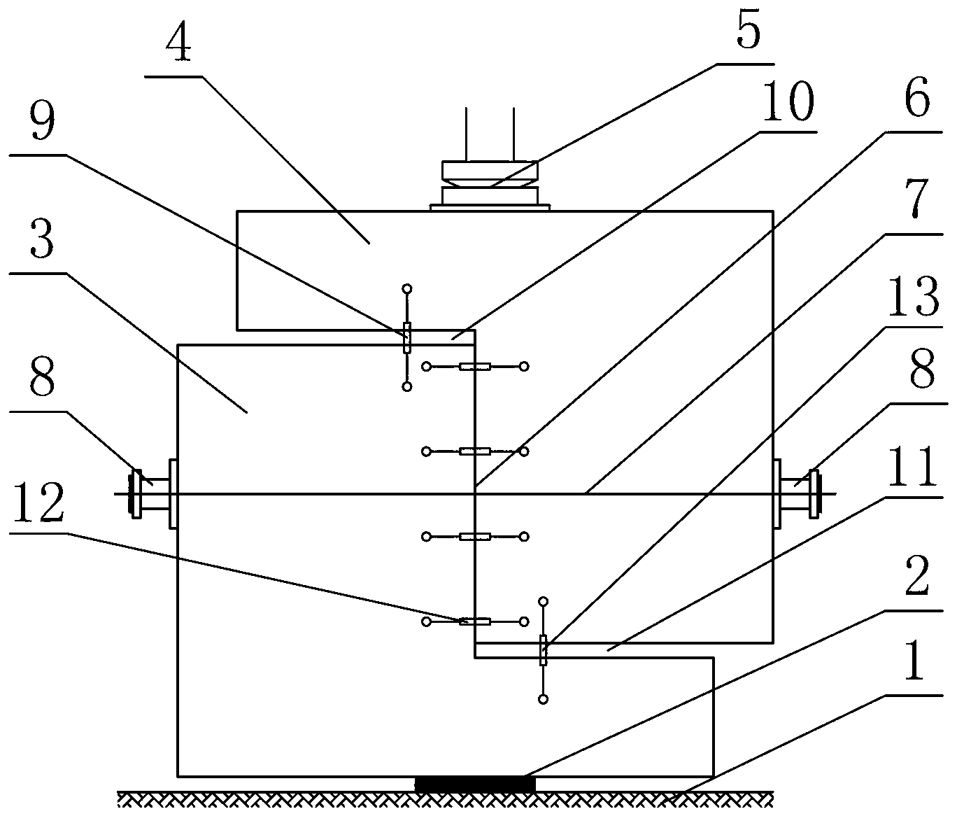
[0032] Embodiment 2: other parts are the same as Embodiment 1, the difference is that the inner surface of the first segment member 3 forming the vertical joint is opposite to the second segment member 4 and is provided with a shear key, such as image 3 shown.

Embodiment 3

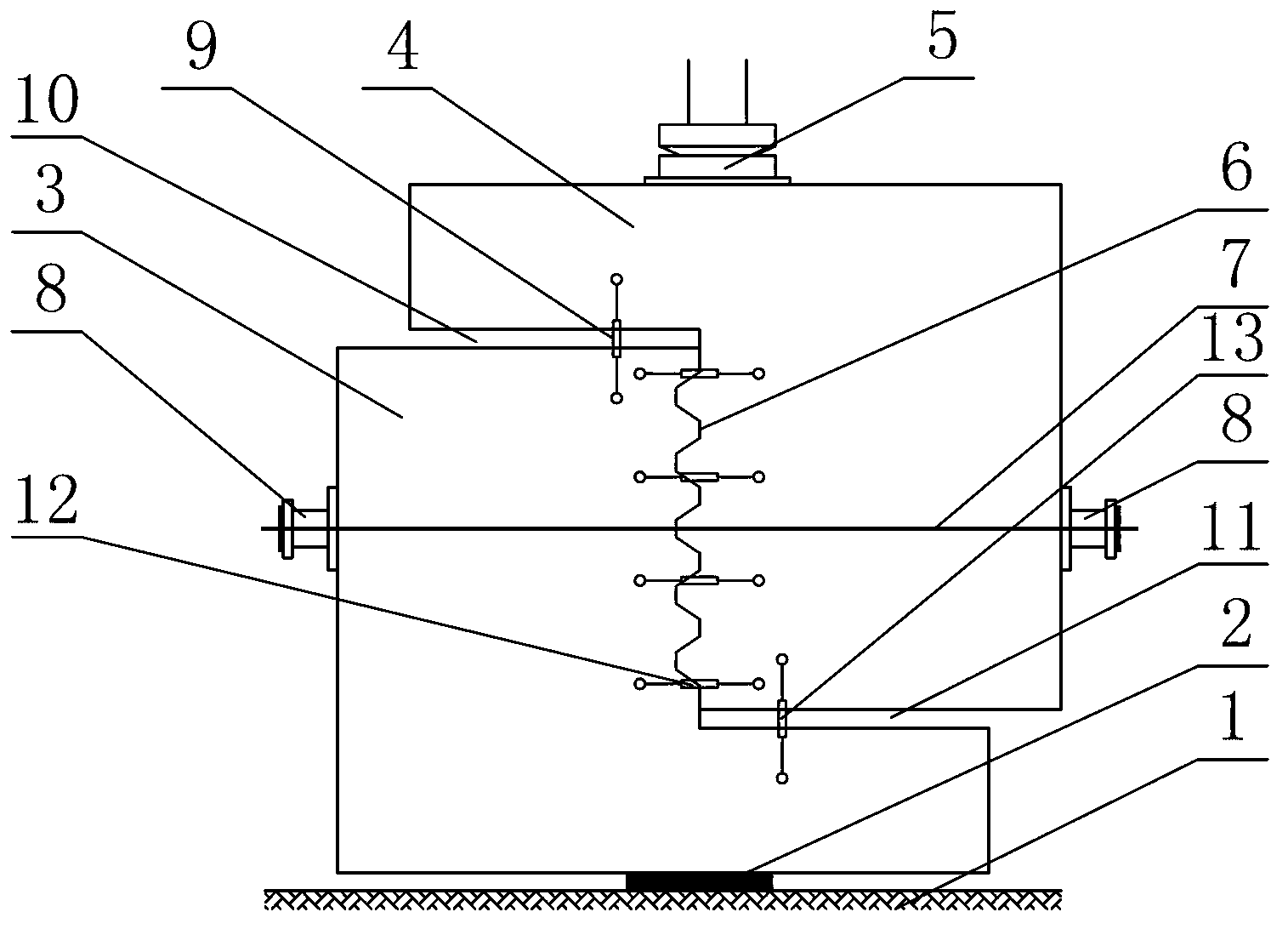
[0033] Embodiment three: other parts are the same as embodiment one, the difference is that the vertical seam 6 is a wet seam, such as Figure 4 As shown, where the wet joint is filled with concrete or mortar or epoxy glue.


PUM


Abstract

The invention discloses a device for testing shear strength of a joint of an external prestressing prefabrication and assembly concrete member. The device disclosed by the invention is characterized in that a first segment of the concrete member is arranged on a support, a hydraulic jack is loaded on the upper end face of a second segment of the concrete member; the cross section of the first segment of the concrete member is of an L shape, the cross section of the second segment of the concrete member is of an inverted L shape, the first segment of the concrete member and the second segment of the concrete member are assembled into a vertical joint, an upper horizontal plane joint and a lower horizontal plant joint by virtue of a post-tensioning prestressing tension device, the upper horizontal plane joint and the lower horizontal plane joint are respectively connected with at least one vertically arranged displacement sensor in a bridging manner, and the vertical joint is connected with one group of displacement sensors horizontally arranged in a bridging manner; and the center connecting line of the support and the hydraulic jack is coincided with that of the vertical joint. The device disclosed by the invention has the advantages that the bending moment of a loaded concrete member can be avoided, pure shear loading is realized, the displacement sensors are arranged at the joint, double control on loading is carried out by virtue of a force and displacements, and the loading failure time can be timely known, so that the device disclosed by the invention has certain safety.

Description

technical field [0001] The invention relates to a joint shear strength test device of concrete components, in particular to a joint shear strength test device of prefabricated assembled concrete components. Background technique [0002] During the construction of sea-crossing bridges, cross-line bridges, and industrial and civil building structures, projects with narrow construction space, short construction period and high construction quality requirements are often encountered. It is difficult for ordinary cast-in-place concrete structures to meet the construction requirements, so The construction of prefabricated assembled concrete elements came into being. [0003] The construction of prefabricated assembled concrete components transfers most of the on-site construction work to the prefabrication factory, replaces the manual construction with mechanized construction, and then transports it to the site for installation and construction, reducing the temporary works such a...

Claims


Application Information

Patent Timeline
Patent Type & Authority Applications(China)
IPC IPC(8): G01N3/24
Inventor 布占宇胡磊刘珍昆金俊杰陈芝唐
Owner NINGBO UNIV
Why Eureka
Try Eureka