Self-centering anti-bending and anti-twisting high-temperature clamp capable of bearing axial tensile load

An axial stretching and self-aligning technology, applied in the anti-torsion high-temperature fixture and self-aligning anti-bending field, can solve the problems of large deviation of axial stress/strain test results, waste of test resources, and cumbersome operation process. Achieve the effect of saving coaxiality alignment work, reducing test costs and flexible operation

Active Publication Date: 2021-03-19
AVIC BEIJING INST OF AERONAUTICAL MATERIALS
View PDF7 Cites 2 Cited by
  • Summary
  • Abstract
  • Description
  • Claims
  • Application Information

AI Technical Summary

Problems solved by technology

It can be seen that the high-temperature test standards for materials clearly stipulate the coaxiality of the testing machine, fixtures and samples to be tested, so as to prevent unexpected bending and torsional deformation of the samples to be tested during the test, thus affecting the Accuracy and reliability of axial mechanical property data of materials
In the actual test process, it is difficult to track and monitor the coaxiality of the testing machine, the fixture and the sample to be tested in real time. Even with some experience, the operation process is very cumbersome, time-consuming and labor-intensive, and the test efficiency is low and the effect is relatively low. Difference
If the coaxiality of the testing machine, fixture and the sample to be tested is not tested and corrected, the bending moment and torque caused by unexpected bending and torsion will have a great impact on the axial loading of the sample, resulting in axial Stress / strain test results have large deviations, so that the obtained test data is judged to be invalid according to the test standard, resulting in a waste of test resources

Method used


Image

  • Self-centering anti-bending and anti-twisting high-temperature clamp capable of bearing axial tensile load
  • Self-centering anti-bending and anti-twisting high-temperature clamp capable of bearing axial tensile load
  • Self-centering anti-bending and anti-twisting high-temperature clamp capable of bearing axial tensile load

Examples


Embodiment Construction

[0028] The device of the present invention will be described in further detail below in conjunction with the accompanying drawings and embodiments:

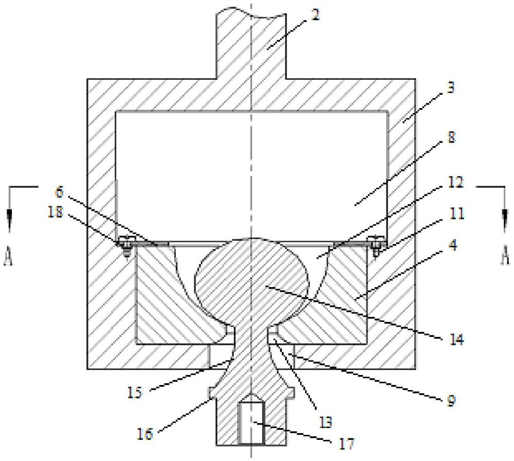
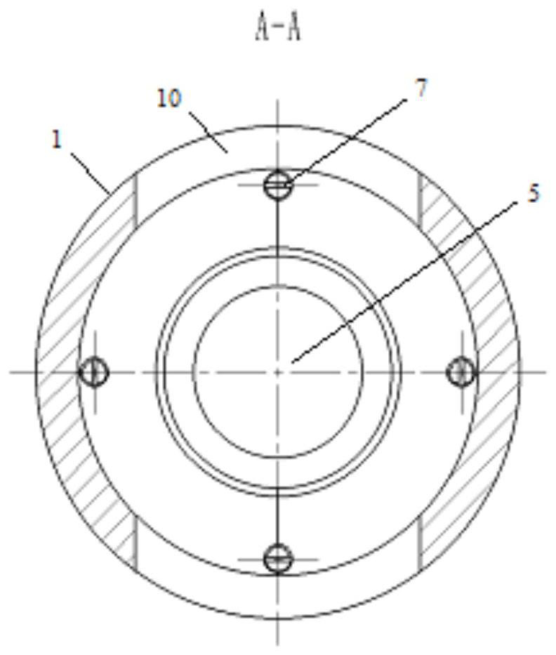
[0029] Refer to the attached Figure 1-Figure 4 As shown in the figure, the outer contour 1 of the self-centering anti-bending and anti-torsion high-temperature clamp bearing axial tensile load is cylindrical, including a load-bearing connecting rod 2, a load-bearing frame 3, a load-bearing block 4, and a rotating support 5. Position the gasket ring 6 and the fastening screw 7.

[0030] The load-bearing connecting rod 2 is a cylindrical structure, one end is connected with the main shaft of the testing machine, and the other end can be connected with the load-bearing frame 3 by welding or integral casting and forging to ensure that the load-bearing connecting rod 2 and the load-bearing frame 3 are connected. The coaxiality of the frame 3 meets the requirements of the test standard.

[0031] The load-bearing frame 3 is a hollow ...


PUM


Abstract

The invention provides a self-centering anti-bending and anti-twisting high-temperature clamp capable of bearing the axial tensile load, the elliptic ball head of the rotary support is in contact fitwith the curved surface of the ellipsoidal cavity of the force bearing block, so that the relative sliding and rotating functions of the elliptic ball head of the rotary support and the ellipsoidal cavity of the force bearing block can be realized; when the coaxiality of the testing machine, the clamp and the to-be-tested sample is inconsistent, the coaxiality of the loading line can be automatically achieved through coordination of sliding and rotating, meanwhile, unexpected bending moment and torque are effectively avoided, a large amount of coaxiality centering work is saved, and the test efficiency is effectively improved. In addition, transition clamps containing different pin holes and internal threaded holes can be designed for flat plate samples with different thicknesses and roundrod samples with different diameters to carry out high-temperature tests, and simplicity, convenience and flexibility are achieved.

Description

technical field [0001] The invention is a self-centering anti-bending and anti-torsion high-temperature clamp for bearing axial tensile load, belonging to the technical field of high-temperature structural material mechanical performance testing. Background technique [0002] Aero-engine turbine components are usually subjected to high temperature during service. In particular, turbine rotor blades must not only withstand high temperature, but also centrifugal loads caused by their high-speed rotation. It can be seen that the high-temperature structural materials of turbine components need to carry out mechanical property tests under high temperature conditions, such as axial tensile, tensile-tension fatigue and endurance / creep tests, etc., so as to provide technical support for the structural design and strength evaluation of turbine components. [0003] During conventional high-temperature tensile, tensile-tension fatigue and endurance / creep testing, the specimen to be tes...

Claims


Application Information

Patent Timeline
Patent Type & Authority Applications(China)
IPC IPC(8): G01N3/04
CPCG01N3/04G01N2203/0423
Inventor 董成利洪建锋李兴无
Owner AVIC BEIJING INST OF AERONAUTICAL MATERIALS
Why Eureka
Try Eureka