System and method for on-line monitoring and alarming of optical fiber loop rolling

A technology of optical fiber ring and optical fiber, which is applied in the field of on-line monitoring and alarm system surrounded by optical fiber, can solve the problems of affecting the accuracy of optical fiber gyroscope, destroying the symmetrical arrangement of optical fiber quadrupoles, and easy fatigue of human eye observation, so as to reduce the Shupe effect and facilitate Analyze the effect of monitoring and reducing errors

Active Publication Date: 2014-12-24
BEIHANG UNIV
View PDF5 Cites 1 Cited by
  • Summary
  • Abstract
  • Description
  • Claims
  • Application Information

AI Technical Summary

Problems solved by technology

However, the length of the optical fiber ring ranges from hundreds of meters to thousands of meters, and it takes about 3 to 8 hours to circle the ring. Human eyes are prone to fatigue when observing; in addition, the diameter of the optical fiber is on the order of microns. It is difficult to make accurate judgments when observing, and it will eventually destroy the four-pole symmetrical arrangement of the optical fiber and affect the accuracy of the fiber optic gyroscope.

Method used


Image

  • System and method for on-line monitoring and alarming of optical fiber loop rolling
  • System and method for on-line monitoring and alarming of optical fiber loop rolling
  • System and method for on-line monitoring and alarming of optical fiber loop rolling

Examples


Embodiment Construction

[0069] The present invention will be further described in detail with reference to the accompanying drawings and embodiments.

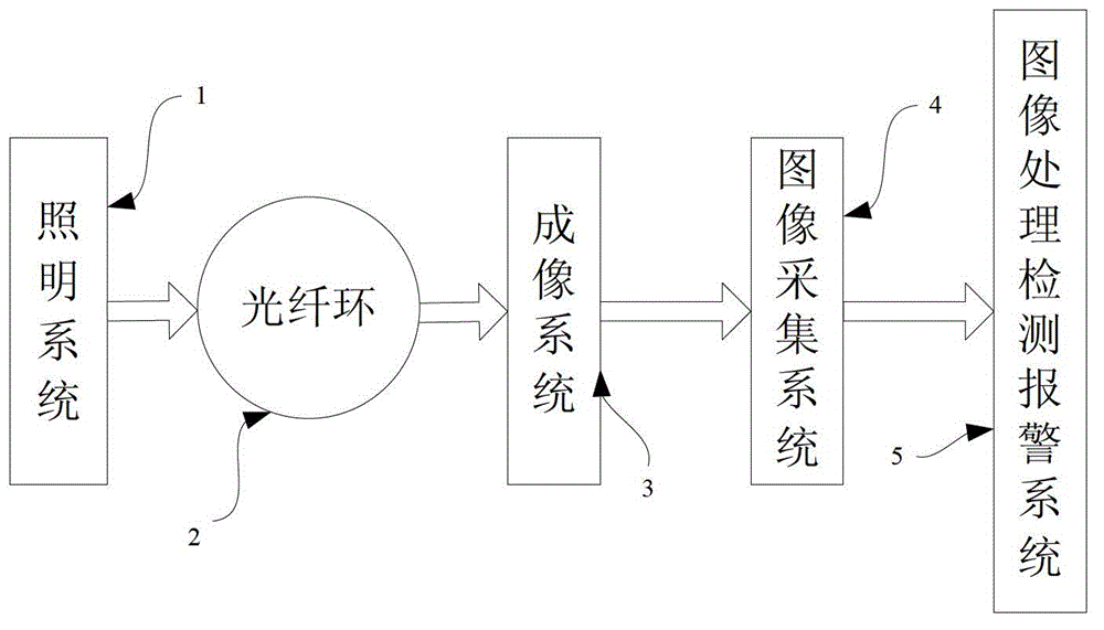
[0070] The invention is an on-line monitoring and alarm system for optical fiber surround system, such as image 3 As shown, it specifically includes an illumination system 1 , an optical fiber ring 2 , an imaging system 3 , an image acquisition system 4 , and an image processing, detection and alarm system 5 .

[0071] The optical fiber ring 2 is an optical fiber ring that is wound in quadrupole symmetry.

[0072] Illumination system 1 adopts flat light source combined with backlighting method for illumination, and the emitted light is irradiated along the tangent direction of fiber ring 2, part of the light is blocked by the side of fiber ring, and shadows are generated by imaging system 3, and the light not blocked by fiber ring passes through Imaging system 3 forms a bright background;

[0073] The light path of the lighting system is characteri...


PUM


Abstract

The invention discloses a system and a method for on-line monitoring and alarming of optical fiber loop rolling. The system comprises an illuminating system, an optical fiber loop, an image acquiring system and an image-processing detecting and alarming system, wherein the image-processing detecting and alarming system comprises an image pre-processing module, an edge information detecting and judging module and a judged result display module. The method comprises the following steps: a first step of setting the number of pre-winding layers; a second step of starting winding and carrying out image acquiring to obtain a shadow curve graph at the tangent line of the optical fiber loop; a third step of pre-processing the image; a fourth step of carrying out optical fiber positioning and edge detecting on the pre-treated image; a fifth step of judging winding superposed fibers; a sixth step of judging winding leaked fibers; and a seventh step of judging after the winding. According to the system and the method for on-line monitoring and alarming of optical fiber loop rolling provided by the invention, fiber leakage and superposition defects which cannot be observed by human eyes in an optical fiber winding process can be real-timely monitored and automatic alarm prompting can be carried out, so that the working efficiency and the quality of the winding can be improved, and the performances of the fiber-optic gyroscope are improved.

Description

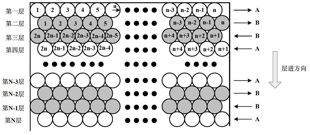
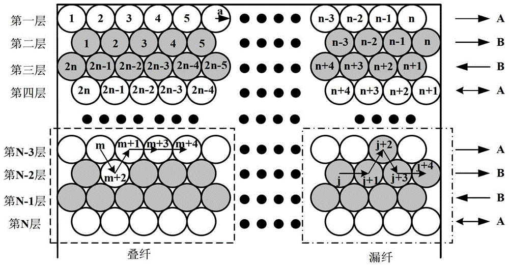
technical field [0001] The invention relates to the technical field of fiber optic gyroscopes, in particular to an on-line monitoring and alarm system and method for fiber optic gyroscopes. Background technique [0002] At present, the four-pole symmetrical winding method is usually used in the winding process of the fiber optic gyro fiber ring, such as figure 1 As shown, it is assumed that there are N layers of fiber rings after winding, and the radius of the fiber is a. The layer feeding direction is from top to bottom, A and B are two fiber supply shafts, winding from the middle of the two fiber supply shafts. The closely arranged optical fibers in each layer are numbered as the first layer, the second layer, the third layer, the fourth layer...the N-3 layer, the N-2 layer, the N-1 layer, and the N layer. If the first layer is A fiber supply axis from left to right, according to the quadrupole symmetrical winding method, the second layer is B fiber supply axis from left...

Claims


Application Information

Patent Timeline
Patent Type & Authority Patents(China)
IPC IPC(8): G01N21/88G01N21/84
Inventor 李彦姜漫李慧鹏宋凝芳杨德伟孟照魁梁正桃
Owner BEIHANG UNIV
Why Eureka
Try Eureka