Acousto-optical detection device and method for shallow buried objects

A technology for detecting devices and buried objects, which is applied in the field of geophysical prospecting, can solve problems such as high directivity and long-distance sound wave emission, and achieve the effect of improving performance

Inactive Publication Date: 2013-04-03
SHANGHAI UNIV
View PDF4 Cites 6 Cited by
  • Summary
  • Abstract
  • Description
  • Claims
  • Application Information

AI Technical Summary

Problems solved by technology

[0004] A typical shallow buried object detection device should include a highly directional acoustic emission system and a non-contact surface vibration detection system. However, the acoustic emission systems currently being studied are mostly based on high-power audio systems, which cannot achieve high directivity and long-distance The ground surface vibration detection system is based on the contact speed sensor of the geophone, which cannot perform non-contact detection of the ground surface vibration state. The present invention is aimed at this key technology.

Method used


Image

  • Acousto-optical detection device and method for shallow buried objects
  • Acousto-optical detection device and method for shallow buried objects

Examples


Embodiment 1

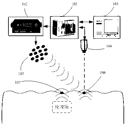
[0021] see figure 1 The structure of the acousto-optic detection device for shallow buried objects includes a computer 101, a signal processor 102, an acoustic parameter array 103, a laser Doppler vibrometer 104 and a data acquisition system 105, and the computer 101 is connected to the data by wires in turn. Acquisition system 105, the signal processor 102 and the acoustic parameter array 103 constitute a highly directional acoustic wave emission system, and the computer 101 constitutes the laser Doppler vibrometer 104 and the data acquisition system 105 Surface vibration detection system.

[0022] The acoustic parameter array 103 and the signal processor 102 used in this embodiment adopt the 24-in diameter Audio Spotlight ultrasonic transducer array (24-in diameter Audio Spotlight ultrasonic transducer array) produced by the American Holosonics Company and its supporting signal processing amplifier (Processor / Amplifier), the data acquisition system adopts the NI-PXI multi-c...

Embodiment 2

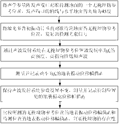
[0024] see figure 2 , the acousto-optic detection method for shallow buried objects adopts the device detection of Embodiment 1, and the detection steps are as follows:

[0025] (1) Align the sounding port of the acoustic parameter array 103 with a reference position 106 without buried objects on the ground to be measured, and the angle between the axis of the sounding port of the acoustic parameter array 103 and the horizontal ground is 45 degrees;

[0026] (2) Align the laser Doppler vibrometer 104 vertically with the reference position 106 without buried objects on the ground to be measured, and emit a detection beam signal;

[0027] (3) The frequency sent by the computer 101 is f 1 with f 2 Two columns of high-frequency sine wave signals, f 1 with f 2 The frequency difference is low frequency f 0 , with a frequency of f 1 with f 2 The two columns of high-frequency sine wave signals are sequentially conditioned and amplified by the data acquisition system 105...


PUM


Abstract

The invention discloses an acousto-optical detection device and a method for shallow buried objects. The acousto-optical detection device comprises an acoustic wave emission system and a to-be-detected earth surface vibration detection device, wherein the acoustic wave emission system comprises a computer, a data acquisition card (DAQ), a signal process amplifier and an acoustic parametric array; and the to-be-detected earth surface vibration detection device comprises an acoustic wave emission system, a laser Doppler vibrometer, a DAQ and a computer. The acoustic wave emission system emits high-directivity high-frequency acoustic waves and generates low-frequency acoustic waves at positions of to-be-detected earth surfaces, and the earth surface vibration detection device detects vibration displacement change conditions at the positions of the to-be-detected earth surfaces. By means of the acousto-optical detection device and the method, non-contact, high-accuracy and rapid measurement for shallow underground buried objects can be achieved.

Description

technical field [0001] The invention relates to the technical field of geophysical prospecting, in particular to an acoustic wave detection device and method in the detection of shallow underground buried objects. Background technique [0002] The safe and reliable detection of shallow underground buried objects such as non-metallic landmines has always been a bottleneck problem in the world. Commonly used metal detectors can only detect buried objects made of metal materials because they are based on the principle of electromagnetic induction, and have poor detection effects on non-metal mines such as plastics with little metal content. For imaging technologies such as infrared, ground penetrating radar, and X-ray, it is difficult to distinguish the type of buried objects in terms of detection mechanism; for non-imaging technologies, such as neutron analysis, it has a strong ability to identify by detecting the chemical properties of materials, but the system It is particu...

Claims


Application Information

Patent Timeline
Patent Type & Authority Applications(China)
IPC IPC(8): G01V1/00
Inventor 王驰周瑜秋丁卫沈高炜吴文雯
Owner SHANGHAI UNIV
Why Eureka
Try Eureka