

Sound-seismic coupling efficiency measuring device and measuring method
A coupling efficiency and measurement device technology, applied in the field of geophysical prospecting, can solve the problems of non-contact detection of surface vibration velocity, inability to achieve high directivity, long-distance sound wave emission, etc., and achieve the effect of improving system performance
- Summary
- Abstract
- Description
- Claims
- Application Information
AI Technical Summary
Problems solved by technology
Method used
Image

Examples
Embodiment 1
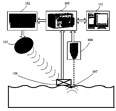
[0021] Embodiment one: see figure 1 The structure of the local surface acoustic-seismic coupling efficiency non-contact measurement device includes a computer 101, a signal processor 102, an acoustic parameter array 103, a Doppler vibrometer 104, a data acquisition card 105 and a sound level meter 106, and the computer 101 is sequentially Connect the data acquisition card 105, the signal processor 102 and the acoustic parameter array 103 through a data line to form an acoustic emission system; The computer 101 constitutes a sound pressure level detection system; the Doppler vibrometer 104 is sequentially connected to the data acquisition card 105 and the computer 101 through a data line to constitute a surface vibration detection system.
[0022] The acoustic parameter array 103 and the signal processor 102 used in this embodiment adopt the 24-in diameter Audio Spotlight ultrasonic transducer array (24-in diameter Audio Spotlight ultrasonic transducer array) produced by the Am...
Embodiment 2
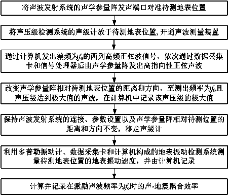
[0023] Embodiment two: see figure 2 , the local surface acoustic-seismic coupling efficiency non-contact measurement method, adopting the device of embodiment one to measure and calculate the surface acoustic-seismic coupling efficiency, the measurement steps are as follows:
[0024] (1) Align the sounding port of the acoustic parameter array 103 of the sound wave emission system with the surface position 107 to be measured;
[0025] (2) Place the sound level meter 106 of the sound pressure level detection system at the position 107 on the ground surface to be measured;
[0026] (3) The difference frequency sent by the computer 101 is f 0 The two columns of high-frequency sine wave signals pass through the data acquisition card 105 and the signal processor 102 in turn, and the acoustic parameter array 103 sends out a high-directivity sine wave;
[0027] (4) Change the distance and direction of the acoustic parameter array 103 relative to the surface location 107 to be meas...
PUM
 Abstract
Description
Claims
Application Information