
Light source device, projector, and light source device fabrication method

A light source device and technology of light source, which can be applied in the parts of lighting device, projection device, lighting device, etc., can solve the problem of laser misradiation and other problems

Active Publication Date: 2013-04-03
CASIO COMPUTER CO LTD
View PDF6 Cites 12 Cited by
  • Summary
  • Abstract
  • Description
  • Claims
  • Application Information

AI Technical Summary

Problems solved by technology

[0006] However, in the laser light source device disclosed in Japanese Patent Application Laid-Open No. 2009-246040, there is a possibility that a light source element such as a semiconductor laser light emitting element is intentionally taken out from the device and diverted to another use, and the laser may be mistakenly used. Adverse conditions such as radiation

Method used


Image

  • Light source device, projector, and light source device fabrication method
  • Light source device, projector, and light source device fabrication method
  • Light source device, projector, and light source device fabrication method

Examples


Embodiment Construction

[0023] Embodiments of the present invention will be described with reference to the drawings.

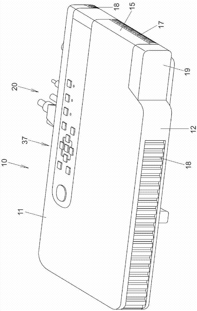
[0024] Hereinafter, the form for carrying out this invention is demonstrated. figure 1 It is an external perspective view of the projector 10 . In the present embodiment, left and right of the projector 10 means the left and right directions with respect to the projection direction, and front and rear means the front and rear directions with respect to the screen side direction of the projector 10 and the traveling direction of the light beam.

[0025] And, the projector 10 such as figure 1 As shown, it has a substantially rectangular parallelepiped shape. On the side of the front panel 12 as the front side plate of the projector housing, there is a lens cover 19 covering the projection port. hole 18. Furthermore, although not shown in figure, the IR receiving part which receives the control signal from a remote controller is provided.

[0026] In addition, a key / indicator porti...


PUM


Abstract

A light source device has a laser light emitting element including a cylinder portion, a flange portion and lead wire terminals, a collimator lens, a collimator lens holder including a collimator lens mounting depressed portion and a hole portion communicating with the depressed portion and accommodating the cylinder portion, and a light source element holder holding the laser light emitting element and including a lead wire outlet hole portion accommodating the lead wire terminals and penetrating from a front surface to a rear surface, and a front surface of the flange portion is fastened by the perimeter of a rear end of the hole portion to press the laser light emitting element against the front surface of the light source element holder to thereby fix the laser light emitting element to the light source element holder, an adhesion fixing member being filled in the lead wire outlet hole portion.

Description

[0001] This application claims priority based on Japanese Patent Application No. 2011-204429 filed on September 20, 2011, the entire content of which is incorporated herein. technical field [0002] The present invention relates to a light source device, a projector, and a manufacturing method of the light source device. Background technique [0003] Currently, a data projector is widely used as an image projection device for projecting a screen of a personal computer, a video image, and an image formed from image data stored in a memory card or the like on a screen. This projector is a device that condenses light emitted from a light source onto a micromirror display element called a DMD (Digital Micromirror Device) or a liquid crystal panel, and displays a color image on a screen. [0004] Among such projectors, the structure using a high-intensity discharge lamp as a light source has been the mainstream in the past, but in recent years, various projectors using light-emit...

Claims


Application Information

Patent Timeline
Patent Type & Authority Applications(China)
IPC IPC(8): G03B21/20G03B21/14G02B27/30F21V9/10F21V9/40
CPCG03B21/20G03B21/204G03B21/2066Y10T29/4978H01S5/02H01S5/02212H01S5/02253H01S5/02345H01S5/02355H01S5/0236
Inventor 肥后富男
Owner CASIO COMPUTER CO LTD
Learn More