High-density chip radiating method by dual-path heat transfer
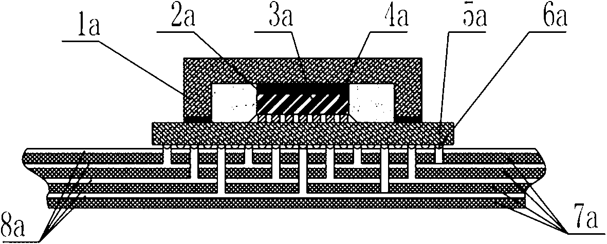
A chip heat dissipation, high-density technology, applied in circuits, cooling/ventilation/heating transformation, instruments, etc., can solve the problem of the chip substrate 5a's heat dissipation potential not being fully utilized, to reduce the heat flow density, improve the heat dissipation capacity, and solve the problem of heat dissipation. cumulative effect
Active Publication Date: 2013-04-03
NO 709 RES INST OF CHINA SHIPBUILDING IND CORP
View PDF3 Cites 27 Cited by
- Summary
- Abstract
- Description
- Claims
- Application Information
AI Technical Summary
Problems solved by technology
This fully shows that the heat transfer capability of the chip core chip 3a to the chip substrate 5a is much greater than the heat transfer capability of the core chip 3a to the chip cover 1a, and the heat dissipation potential in the direction of the chip substrate 5a has not been brought into play
Method used
View moreImage
Smart ImageViewing Examples
Examples
Embodiment Construction
Login to View More PUM
 Abstract
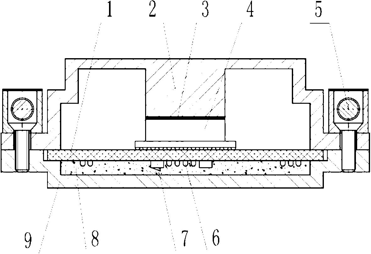
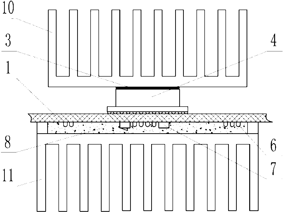
Disclosed is a high-density chip radiating method by dual-path heat transfer. Each heat transfer path comprises a chip, a printed board, thermally conductive and insulating media and radiators. The high-density chip radiating method is characterized by including the steps: firstly, welding the chips on the printed boards; secondly, mounting the radiators on the surfaces of the chips and bottom surfaces of the printed boards; and finally, filling the thermally conductive and insulating media among the chips and the radiators and among the printed boards and the radiators. The high-density chip radiating method has the advantages that heat on the heat transfer paths of the chips is distributed by setting up two parallel heat transfer paths, the thermal flux density on the heat transfer paths is reduced, the radiating capacity of the chips can be improved, the problem of thermal accumulation of the high-density chips is solved, and the core temperature of the chips is reduced.
Description
technical field [0001] The invention relates to the technical field of electronic heat dissipation, in particular to a high-density chip heat dissipation method using dual-path heat transfer. Background technique [0002] With the increasing functions of computers and the development of high-frequency trends, modern computers have higher and higher heat dissipation requirements for important components. In addition to CPUs, motherboards, north bridge chipsets, and graphics cards all have high heat dissipation requirements. There are many ways for computers to dissipate heat. At present, there are mainly air cooling, liquid cooling, semiconductor cooling, and heat pipe conduction. But no matter what kind of heat dissipation method, a radiator will be mounted on the surface of the heating chip. The difference is the form of the radiator, which is plate-shaped, rib-shaped, fin-shaped, embedded heat pipe or embedded liquid cooling. manage. However, these heat dissipation metho...
Claims
Login to View More Application Information
Patent Timeline
 Patent Type & Authority Applications(China)
IPC IPC(8): H01L21/48H01L23/34H05K7/20G06F1/20
Inventor 严红李强
Owner NO 709 RES INST OF CHINA SHIPBUILDING IND CORP
Features
- R&D
- Intellectual Property
- Life Sciences
- Materials
- Tech Scout
- Unparalleled Data Quality
- Higher Quality Content
- 60% Fewer Hallucinations
Learn More Browse by: Latest US Patents, China's latest patents, Technical Efficacy Thesaurus, Application Domain, Technology Topic, Popular Technical Reports.
© 2025 PatSnap. All rights reserved.Legal|Privacy policy|Modern Slavery Act Transparency Statement|Sitemap|About US| Contact US: help@patsnap.com


