Wafer boat that prevents sagging at the center of the wafer

A central part and wafer technology, which is applied in the field of devices carrying wafers, can solve the problems of sagging of the central part and deformation of the wafer, and achieve the effect of preventing the movement of the wafer boat, preventing sagging and deformation, and avoiding shaking.

Active Publication Date: 2016-12-28
SHANGHAI HUAHONG GRACE SEMICON MFG CORP
View PDF5 Cites 0 Cited by
  • Summary
  • Abstract
  • Description
  • Claims
  • Application Information

AI Technical Summary

Problems solved by technology

[0004] The technical problem to be solved by the present invention is that the central part of the wafer will sag when placed in the existing wafer boat, which will cause the deformation of the entire wafer

Method used


Image

  • Wafer boat that prevents sagging at the center of the wafer
  • Wafer boat that prevents sagging at the center of the wafer
  • Wafer boat that prevents sagging at the center of the wafer

Examples


Embodiment 1

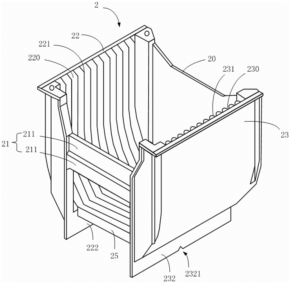
[0025] Please refer to image 3 , image 3 The wafer boat 2 provided by the embodiment of the present invention. The wafer boat 2 has a main body formed by a front side wall 20 , a rear side wall 21 , a left side wall 22 and a right side wall 23 . The body defines an interior compartment area. In the inner compartment area, the inner surface of the left side wall 22 includes a plurality of left inner wings 221 , and these left inner wings 221 define a plurality of left placement slots 220 . Likewise, the inner side of the right side wall 23 includes a plurality of right inner wings 231 , and the right inner wings 231 define a plurality of right placement slots 230 . In this embodiment, the left inner wing 221 protrudes from the inner side of the left side wall 22, while the right inner wing 231 extends out of the inner side of the right side wall 23, and the corresponding left inner wing 221 and the corresponding right inner wing 231 The connection forms an integral inner ...

Embodiment 2

[0033] Please refer to Figure 5 , Figure 5 It is a top view of the wafer boat 3 that prevents the central part of the wafer from drooping for the second embodiment of the present invention. Most of the structures of the wafer boat 3 in this embodiment are the same as that of the wafer boat 3 described in Embodiment 1. The difference is that in this embodiment, only the left inner wing 321 on the inner surface of the left side wall 32 is extended for a certain distance ( Can refer to comparison figure 2 ). A section of the inner wing formed by the extension is marked as the bottom inner wing 35, and the bottom inner wing 35 also increases the length of the contact side between the wafer placed in the wafer boat 3 and the wafer boat 3, so that the center of the wafer is drooped. Improve the appearance and prevent the deformation of the wafer.

[0034] Although not shown in the figure, in other embodiments of the present invention, the right inner wing can also be extended...


PUM


Abstract

The invention provides a wafer boat for preventing the central portion of a wafer from sagging. The wafer boat comprises a main body formed by a front sidewall, a rear sidewall, a left sidewall and a right sidewall. An internal spacer region is defined by the main body. In the internal spacer region, the inner surface of the left sidewall comprises a plurality of left holding grooves defined by a plurality of left inner wings, the inner surface of the right sidewall comprises a plurality of right holding grooves defined by a plurality of right inner wings, the left holding grooves correspond to the right holding grooves one by one, one sections of the left inner wings extend out of the inner surface of the left sidewall or one sections of the right inner wings extend out of the inner surface of the right sidewall, or one sections of the left inner wings extend out of the inner surface of the left sidewall and one sections of the right inner wings simultaneously extend out of the inner surface of the right sidewall. The wafer boat is capable of effectively preventing the central portion of the wafer therein from sagging.

Description

technical field [0001] The invention relates to a device for carrying wafers, in particular to a wafer boat which prevents the central part of the wafer from drooping. Background technique [0002] A wafer boat is a device used for storing and transporting wafers. Usually, the wafer boat contains multiple wafer placement slots (slots), and each wafer placement slot can hold a wafer. Please refer to figure 1 and figure 2 , figure 1 It is the three-dimensional structure of the existing crystal boat structure, figure 2 It is a top view of the existing crystal boat. From figure 1 It can be seen from the figure that the existing wafer boat 1 mainly includes a front side wall 10 , a rear side wall 11 , a left side wall 12 and a right side wall 13 . The four sidewalls jointly define a space where the wafers can be placed parallel to each other. On the left side wall 12 and the right side wall 13 of the existing crystal boat, there are also a footstand (left footrest 122 an...

Claims


Application Information

Patent Timeline
Patent Type & Authority Patents(China)
IPC IPC(8): H01L21/673
Inventor 傅荣颢黄锦才
Owner SHANGHAI HUAHONG GRACE SEMICON MFG CORP
Why Eureka
Try Eureka