Bootstrap capacitor power failure restoring circuit and switch power source circuit

A switching power supply circuit, bootstrap capacitor technology, applied in circuits, electrical components, output power conversion devices, etc., can solve the problem of bootstrap capacitors not being able to charge, charging

Active Publication Date: 2013-04-03
SILERGY SEMICON TECH (HANGZHOU) CO LTD
View PDF4 Cites 15 Cited by
  • Summary
  • Abstract
  • Description
  • Claims
  • Application Information

AI Technical Summary

Problems solved by technology

[0006] The invention provides a bootstrap capacitor power-down recovery circuit, which can effectively solve the problem that

Method used


Image

  • Bootstrap capacitor power failure restoring circuit and switch power source circuit
  • Bootstrap capacitor power failure restoring circuit and switch power source circuit
  • Bootstrap capacitor power failure restoring circuit and switch power source circuit

Examples


Embodiment 1

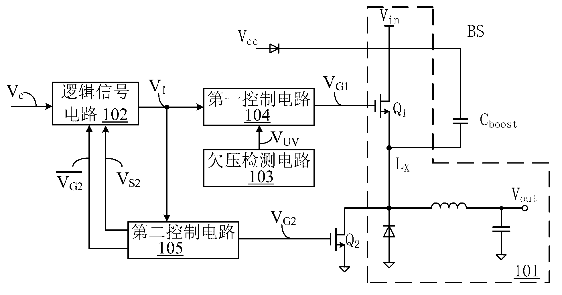
[0038] refer to image 3 , shows a functional block diagram of the bootstrap capacitor power-down recovery circuit in Embodiment 1 of the present invention, the bootstrap capacitor power-down recovery circuit is used in a switching power supply circuit, and the switching power supply circuit includes a first switching tube Q 1 .

[0039] The bootstrap capacitor power-down recovery circuit includes: a bootstrap capacitor C boost , the second switching tube Q 2 , a logic signal circuit 102 , an undervoltage detection circuit 103 , a first control circuit 104 and a second control circuit 105 . in,

[0040] The undervoltage detection circuit 103 is used to determine the bootstrap capacitor C boost Whether the voltage at both ends is in the undervoltage state, and output the detection signal V uv used to characterize the bootstrap capacitor C boost The voltage state of both ends.

[0041] The logic signal circuit 102, when the bootstrap capacitor C boost When the voltage at...

Embodiment 2

[0048] refer to Figure 4A , is a schematic diagram of a bootstrap capacitor power-down recovery circuit according to an embodiment of the present invention, still including the logic signal circuit 102, the undervoltage detection circuit, the first control circuit 104 and the second control circuit 105 . and image 3 The difference between the shown embodiments is that this embodiment provides the specific implementation manners of the logic signal circuit 102, the first control circuit 104 and the second control circuit 105, which will be described below in conjunction with the accompanying drawings. A detailed description is provided to facilitate a better understanding of the circuit structure and working principle of the bootstrap capacitor power-down recovery circuit according to an embodiment of the present invention.

[0049] Specifically, the logic signal circuit 102 in this embodiment includes: a first flip-flop RS 1 , OR gate and first AND gate.

[0050] An inpu...


PUM


Abstract

The invention provides a bootstrap capacitor power failure restoring circuit and a switch power source circuit. The bootstrap capacitor power failure restoring circuit comprises a bootstrap capacitor, a second switch tube, a logic signal circuit, an undervoltage detecting circuit, a first control circuit and a second control circuit. When voltage at two ends of the bootstrap capacitor is in undervoltage state, on and off of the first switch tube are controlled according to a first control signal, and meanwhile, the second switch tube is kept off. When voltage of two ends of the bootstrap capacitor is in undervoltage state, the first switch tube is switched off, and when effective time of the first control signal is up to a first preset time, the second switch tube is conducted, the bootstrap capacitor is started to be charged, and the second switch tube is switched off after a second preset time. The bootstrap capacitor is charged by circulating the above steps. The switch power source circuit comprises a power-level circuit and the bootstrap capacitor power failure restoring circuit.

Description

technical field [0001] The invention relates to the field of switching power supplies, in particular to a bootstrap capacitor power-down recovery circuit and a switching power supply circuit. Background technique [0002] Switching power supply is a kind of power supply that uses modern power electronic technology to control the time ratio of switching transistor on and off to maintain stable output. Switching power supply is generally composed of a drive unit (usually driven by pulse width modulation) and a main circuit, with high efficiency. , the advantage of small size. Among them, boost circuit, buck circuit and buck-boost are common main circuit topologies. [0003] Such as figure 1 As shown, for the buck circuit where the upper transistor is an N transistor, in order to prevent the switching transistor Q from being turned off immediately after it is turned on, it is often necessary to equip the switching transistor with a bootstrap capacitor C boost , to provide th...

Claims


Application Information

Patent Timeline
IPC IPC(8): H02M1/08
CPCH02M1/32H02M3/155H03K17/063H03K2217/0081
Inventor 吴惠明
Owner SILERGY SEMICON TECH (HANGZHOU) CO LTD
Why Eureka
Try Eureka