Half-bridge five-electrical-level inverter and high-frequency insulation-type half-bridge five-electrical-level inverter
A five-level, inverter technology, applied in electrical components, AC power input to DC power output, output power conversion devices, etc. The high-frequency isolation type multi-level topology is limited in application occasions, and there are no real multi-level problems, so as to achieve the effect of improving conversion efficiency and power density, good voltage spectrum characteristics, and broadening the selection range.
- Summary
- Abstract
- Description
- Claims
- Application Information
AI Technical Summary
Problems solved by technology
Method used
Image

Examples
Embodiment 1
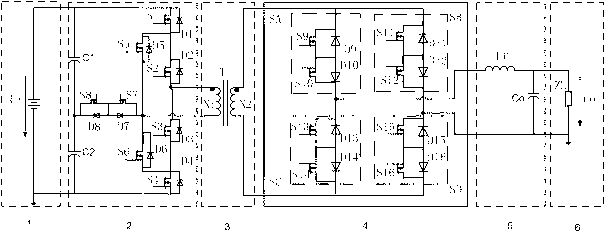
[0025] Example 1: Combining figure 2 , a high-frequency isolated half-bridge five-level inverter is suitable for high-voltage inverter applications with high-frequency electrical isolation. It is a half-bridge circuit topology, that is, the positive pole of the input DC power supply Ui is connected to the first input capacitor C1 The positive pole of the first input capacitor C1, the drain of the first power switch tube S1 is connected to the cathode of the first diode D1, the negative pole of the second input capacitor C2, the source of the fourth power switch tube S4 and the first diode D1 The anodes of the four diodes D4 are connected, the negative pole of the first input capacitor C1, the positive pole of the second input capacitor C2, the drain of the eighth power switching tube S8 and the cathode of the eighth diode D8 are connected together, and the seventh The source of the power switch S7, the source of the eighth power switch S8, the anode of the seventh diode D7 an...
Embodiment 2
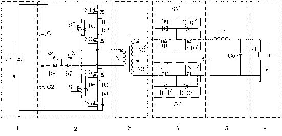
[0026] Example 2: Combining image 3 , a high-frequency isolated half-bridge five-level inverter is suitable for high-voltage inverter applications with high-frequency electrical isolation. It is a half-bridge full-wave circuit topology, that is, the positive pole of the input DC power supply Ui is connected to the first input capacitor The anode of C1, the anode of the first input capacitor C1, the drain of the first power switch S1 are connected to the cathode of the first diode D1, the cathode of the second input capacitor C2, the source of the fourth power switch S4 and The anode of the fourth diode D4 is connected, the negative pole of the first input capacitor C1 is connected, the positive pole of the second input capacitor C2 is connected, the drain of the eighth power switch S8 is connected with the cathode of the eighth diode D8, and the first The source of the seventh power switch tube S7, the source of the eighth power switch tube S8, the anode of the seventh diode ...
PUM
 Abstract
Description
Claims
Application Information
 - R&D
- Intellectual Property
- Life Sciences
- Materials
- Tech Scout
- Unparalleled Data Quality
- Higher Quality Content
- 60% Fewer Hallucinations
Browse by: Latest US Patents, China's latest patents, Technical Efficacy Thesaurus, Application Domain, Technology Topic, Popular Technical Reports.
© 2025 PatSnap. All rights reserved.Legal|Privacy policy|Modern Slavery Act Transparency Statement|Sitemap|About US| Contact US: help@patsnap.com