Radar apparatus

A radar device and gain adjustment technology, which is applied to measurement devices, reflection/re-radiation of radio waves, and utilization of re-radiation, etc., can solve problems such as the influence of received signal signal power, and achieve the effect of reducing signal distortion and improving deterioration.

Active Publication Date: 2013-04-03
PANASONIC CORP
View PDF6 Cites 8 Cited by
  • Summary
  • Abstract
  • Description
  • Claims
  • Application Information

AI Technical Summary

Problems solved by technology

Although the reflection coefficient of radio waves varies depending on the size or shape of the reflector, in radar devices, the distance of the reflector greatly affects the signal power of the received signal

Method used


Image

  • Radar apparatus
  • Radar apparatus
  • Radar apparatus

Examples


no. 1 Embodiment approach

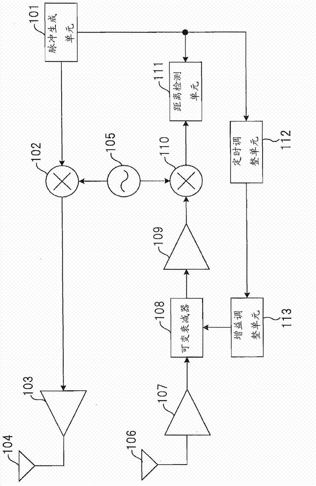
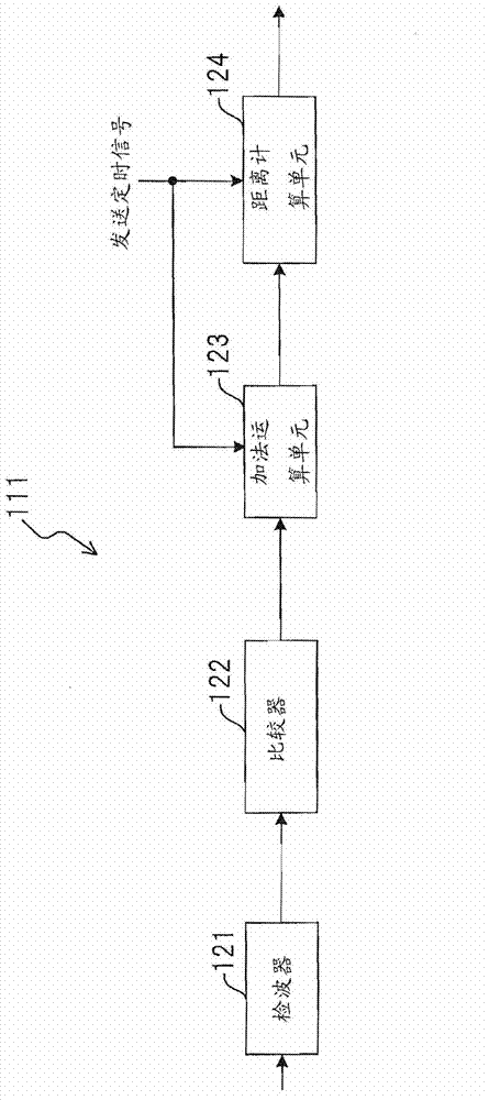
[0069] figure 1 It is a block diagram showing the configuration of the radar device according to the first embodiment of the present invention. As a transmitting part of the radar device, a pulse generation unit 101 , a frequency conversion unit 102 , an amplifier 103 , an antenna 104 , and a local oscillator 105 are included. In addition, as a receiving section of the radar device, an antenna 106 , amplifiers 107 , 109 , variable attenuator 108 , frequency conversion unit 110 , distance detection unit 111 , timing adjustment unit 112 , and gain adjustment unit 113 are included.

[0070] Here, the frequency conversion unit 102, the amplifier 103, and the antenna 104 are set as an example of a structure realizing the function of the radio frequency transmission unit. In addition, an antenna 106, an amplifier 107, and a frequency conversion unit 110 are provided as an example of a structure realizing the function of a radio frequency receiving unit.

[0071] The pulse generat...

no. 2 Embodiment approach

[0128] Figure 8 It is a block diagram showing the configuration of the radar device according to the second embodiment of the present invention. The second embodiment is an example in which the configuration and operation of the distance detecting means in the radar device of the first embodiment are changed. Here, the description will focus on the parts that are different from the first embodiment.

[0129] As a transmitting part of the radar device, a pulse generation unit 101 , a frequency conversion unit 102 , an amplifier 103 , an antenna 104 , and a local oscillator 105 are included. In addition, as a receiving section of the radar device, antenna 106 , amplifiers 107 , 109 , variable attenuator 108 , frequency conversion unit 110 , distance detection unit 211 , timing adjustment unit 112 , and gain adjustment unit 113 are included.

[0130] Distance detection unit 211 takes as input the signal down-converted to baseband by frequency conversion unit 110 , the gain adj...

no. 3 Embodiment approach

[0154] Figure 13 It is a block diagram showing the configuration of a radar device according to a third embodiment of the present invention. The third embodiment is a configuration example of a radar device having a function of measuring the position of a reflector, in which the direction of arrival of a received pulse of a reflected wave is measured using an array antenna for the receiving antenna. Several methods for determining the direction of arrival of an incoming wave are shown below.

[0155] Here, a configuration using a general beamforming method will be described. Note that the beamforming method is not directly related to the present invention, so a detailed description thereof will be omitted here.

[0156]As a transmitting part of the radar device, a pulse generation unit 101 , a frequency conversion unit 102 , an amplifier 103 , an antenna 104 , and a local oscillator 105 are included. In addition, as a receiving section of the radar apparatus, a plurality o...


PUM


Abstract

The influence of a signal distortion, which occurs when the gain of a reception unit in a radar apparatus is adjusted, is reduced, thereby lessening the degradation of received signals. A pulse signal is generated, as a transport signal, by a pulse generating unit (101), and then repetitively transmitted via an antenna (104) at constant time intervals. A received signal, which is received via an antenna (106) and includes a reflected wave having been reflected by an object, is amplified by an amplifier (107) and then gain-adjusted by a variable attenuator (108). Thereafter, a distance detecting unit (111) detects a received pulse of the reflected wave, thereby calculating the distance from the object. The variable attenuator (108) attenuates the received signal by use of the gain that has been adjusted in accordance with a gain control signal supplied from a gain adjusting unit (113). The gain (attenuation amount) of the variable attenuator (108) is controlled in such a manner that the gain becomes largest just after the transmission of the pulse signal and then becomes smaller as time goes by. The gain adjustment timing at which to change the attenuation amount is made different, on the basis of a gain adjustment timing signal from a timing adjusting unit (112), for each transmission of the pulse signal.

Description

technical field [0001] The present invention relates to radar devices, and more particularly to radar devices utilizing broadband pulse technology. Background technique [0002] Conventionally, there are radar devices that specify the position of an object by transmitting radio waves and receiving reflected waves of the transmitted signal that are reflected off the object. Many radar devices of this type use a pulse signal converted to a radio frequency as a transmission signal. The signal power of the pulse signal is attenuated after being transmitted until it is reflected by an object and received again. [0003] Therefore, the closer the power of the received signal is reflected from the object, the larger the reflected wave is, and the more the power of the received signal is reflected from the distant object, the smaller the reflected wave is. Therefore, a radar device requires a circuit for amplifying reflected waves reflected from distant objects. As an amplifier c...

Claims


Application Information

Patent Timeline
IPC IPC(8): G01S7/34G01S7/02G01S7/32
CPCG01S13/42G01S7/2922G01S7/34G01S7/28G01S13/0209
Inventor 向井裕人岸上高明中川洋一
Owner PANASONIC CORP
Why Eureka
Try Eureka