Ring oscillator circuit

a technology of oscillator circuit and ring, which is applied in the direction of pulse generator, pulse generation by logic circuit, pulse technique, etc., can solve the problems of radiated emission, affecting the length of the path affecting the oscillation signal, and failing to output a signal, so as to reduce the distortion of the signal

Inactive Publication Date: 2006-07-18
ROHM CO LTD
View PDF5 Cites 25 Cited by
  • Summary
  • Abstract
  • Description
  • Claims
  • Application Information

AI Technical Summary

Benefits of technology

[0008]Since the distances between the inverting amplifiers are substantially equal to each other, breaking of symmetry such as a relatively long return route from a final stage to a first stage does not occur. Accordingly, signal propagation delays between adjacent inverting amplifiers are uniform so that waveform distortion is reduced. Further, proximity of the final stage to the first stage provides an advantage in that variation in product characteristics is prevented, which additionally reduces waveform distortion.
[0011]The ring oscillation circuit may further comprise a control circuit generating a drive signal to drive the plurality of inverting amplifiers. In this case, signal lines from the control circuit to the plurality of inverting amplifiers may be arranged substantially symmetrically with respect to the outgoing route and the homeward route. This layout is also useful in ensuring that signal propagation characteristic is uniform. The control circuit may be provided between the outgoing route and the homeward route. In this case, it is easy to ensure that the distances from the control circuit to the inverting amplifiers are equal to each other so that the length of control signal lines is uniform from stage to stage. Therefore, this arrangement is also useful in reducing signal distortion.

Problems solved by technology

As the oscillation frequency is increased, the length of this path affects the oscillation signal by introducing jitter or other distortion components.
As a result, the apparatus may fail to output a signal at a desired frequency, or higher harmonics become more noticeable, producing radiated emission.

Method used


Image

  • Ring oscillator circuit
  • Ring oscillator circuit
  • Ring oscillator circuit

Examples


Embodiment Construction

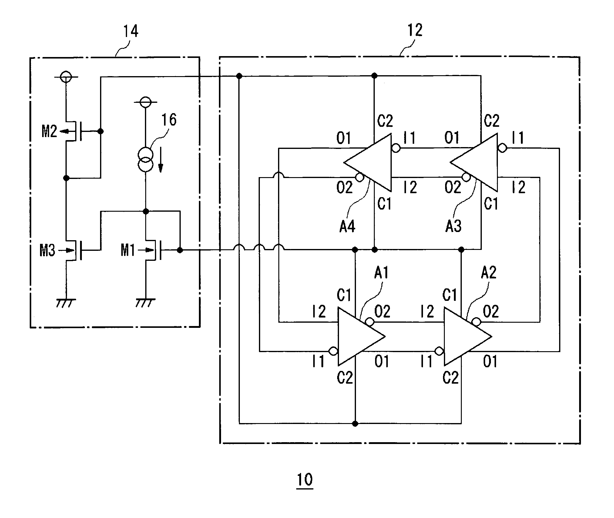
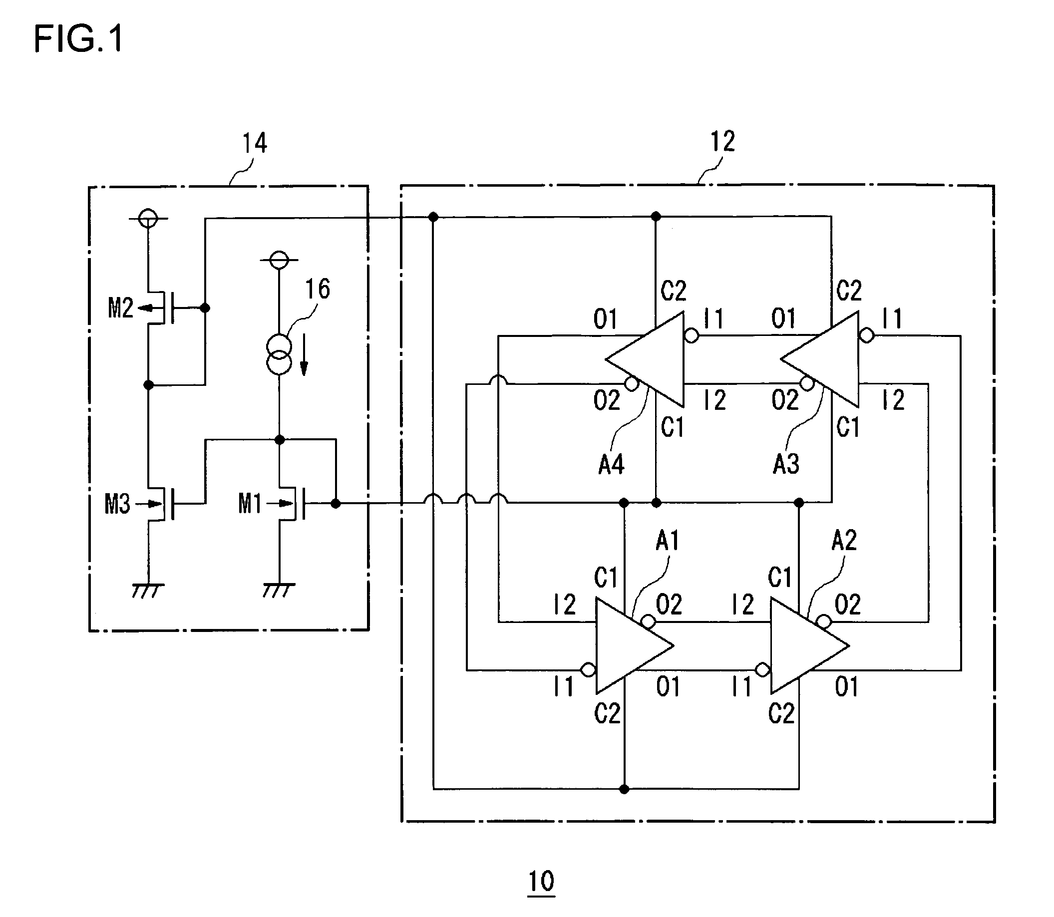
[0020]FIG. 1 shows a ring oscillator circuit 10 according to the embodiment. Referring to FIG. 1, an oscillation unit 12 is provided with four differential amplifiers A1–A4 and oscillates at a predetermined frequency. A control circuit 14 drives the oscillation unit 12 by supplying a drive signal thereto so as to adjust the oscillation frequency of the oscillation unit 12 at a desired value.

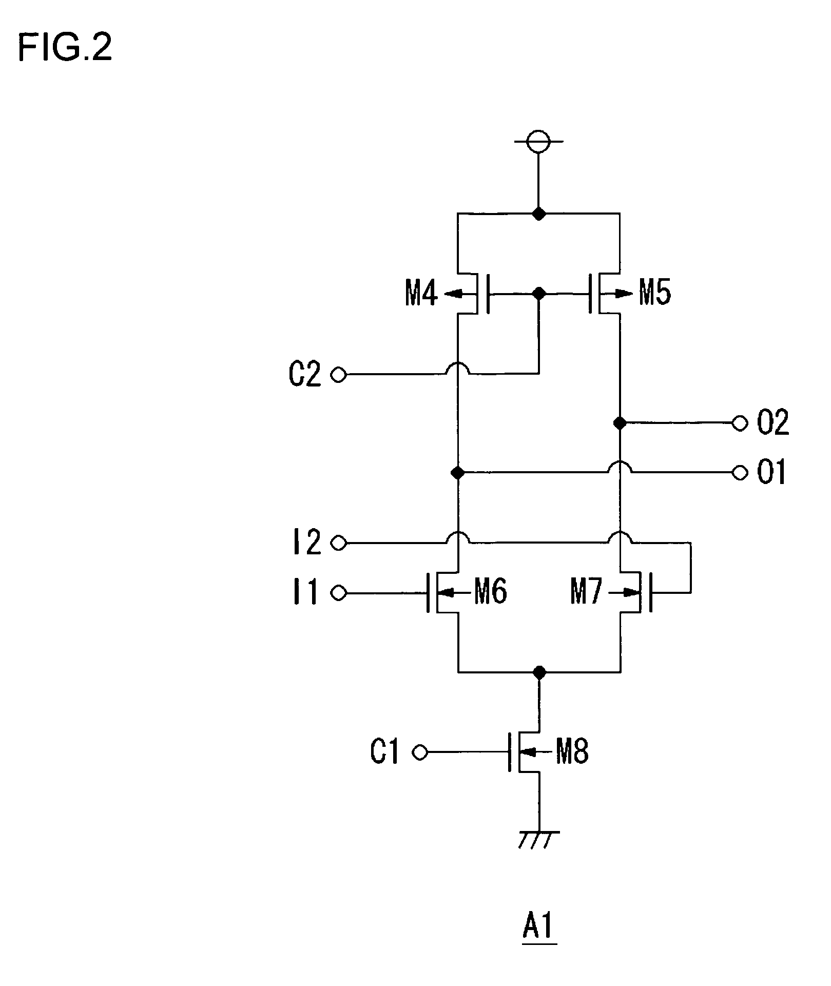
[0021]The differential amplifiers A1–A4 of the oscillation unit 12 are of the same structure. Each of the amplifiers is provided with first and second input terminals I1 and I2, first and second output terminals O1 and O2, and first and second control signal terminals C1 and C2. Each of the amplifiers also has terminals for a power supply VDD and the ground GND. The four differential amplifiers A1–A4 are arranged in the configuration of a ring. The first and second outputs O1 and O2 of each of the amplifiers are connected to the first and second inputs I1 and I2 of the next differential amplifier...


PUM


Abstract

A turn-round is provided in the middle of a plurality of differential amplifiers A1–A4. A first-stage differential amplifier A1 is provided in close proximity to a final-stage differential amplifier A4 so that distances between adjacent differential amplifiers are substantially equal to each other. With this, signal lines between the differential amplifiers are uniform in length and propagation delays are uniform. As a result, a high single-frequency oscillation signal is output.

Description

CROSS-REFERENCE TO RELATED APPLICATION[0001]The present application is a continuation of PCT / JP2004 / 007527, filed on Jun. 1, 2004, the entire contents of which are incorporated herein by reference, and which claims the benefit of the date of the earlier filed Japanese Patent Application No. JP 2003-167029 filed on Jun. 11, 2003.TECHNICAL FIELD[0002]The present invention relates to a ring oscillator circuit and, more particularly, to a ring oscillator circuit provided with a plurality of inverting amplifiers.BACKGROUND TECHNOLOGY[0003]A ring oscillator in which a plurality of inverters are arranged in series to obtain a signal oscillating at a desired frequency and in which an output of a final stage is fed back to a first stage is known. FIG. 8 shows a structure of a ring oscillator circuit as generally known. Five inverters INV1–INV5 are arranged in series, and an output of the final-stage inverter INV5 is fed back to the input of the first-stage INV1. In this example, the oscillat...

Claims


Application Information

Patent Timeline
Patent Type & Authority Patents(United States)
IPC IPC(8): H03B27/00H03K3/03
CPCH03K3/0322
Inventor WAKII, TAKESHI
Owner ROHM CO LTD
Why Eureka
Try Eureka