
combine harvester

A combine harvester and machine body technology, applied in the direction of harvesters, cutters, agricultural machinery and implements, etc., can solve the problems of the posture change of the conveying cylinder, the displacement of the discharge position, the unstable posture of the conveying cylinder, and the loss of grains, etc., to achieve support Effects of increased rigidity, smooth holding, and reliable holding

Inactive Publication Date: 2015-09-23
ISEKI & CO LTD
View PDF7 Cites 0 Cited by
  • Summary
  • Abstract
  • Description
  • Claims
  • Application Information

AI Technical Summary

Problems solved by technology

[0007] However, in the technology described in the above-mentioned Patent Document 1, the rotational position of the conveying cylinder is maintained by frictional force, so there is a disadvantage that the posture of the conveying cylinder is unstable, the posture of the conveying cylinder changes during the discharge operation, or the discharge The position is shifted, which is easy to cause the loss of grain

Method used


Image

  • combine harvester
  • combine harvester
  • combine harvester

Examples


Embodiment Construction

[0065] Embodiments of the present invention will be described by taking an ordinary combine harvester as an example.

[0066] (body structure)

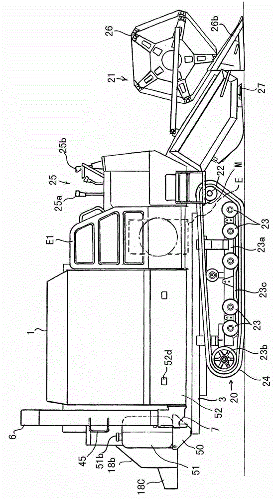
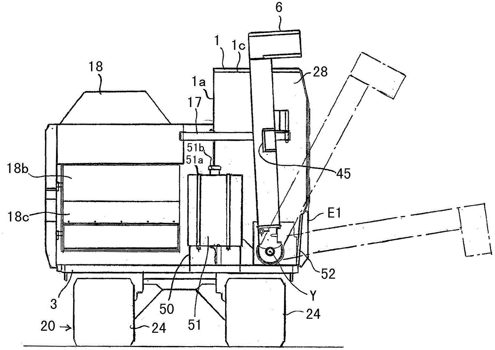
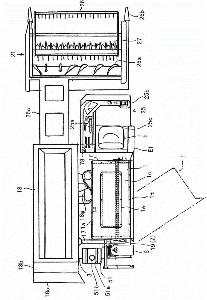
[0067] Such as Figure 1 ~ Figure 3 As shown, the combine harvesting mechanism becomes: a traveling device 20 is provided below the body frame 3, a threshing device 18 is mounted on the upper left side of the body frame 3, and grains are mounted on the upper right side of the body frame 3. The storage device 1 and the conveying cylinder 6 for grain discharge are equipped with an electronic governor type or a common rail fuel injection engine E at the front side of the grain storage device 1 on the body frame 3, and the running device The front position of 20 is provided with the harvesting device 21 that can carry out lifting adjustment freely.

[0068] (Structure of the driving part, running gear and control part)

[0069] Such as figure 1 , image 3 As shown, the engine E is covered by a freely openable and closable engine cove...


PUM


Abstract

PURPOSE: A combine is provided to rotate a grain storage unit including a return container repetitively rotating up-and-down in the circumference of the axis in a front and a rear of a body without interfering with a return container. CONSTITUTION: A combine includes a threshing apparatus(18) installed in one side of left and right sides of a body frame including a traveling apparatus(20); a grain storage unit(1) and a grain discharge return container(6) installed in the left and right sides of a body frame; a maintenance unit installing the return container to be repetitively rotating up-and-down in a first axial circumference in the front and the rear directions of the body to support; a return screw formed between a front wall and a rear wall of the grain storage unit while opening a check unit in a upper wall of the grain storage unit; and a first container member front side unit fixed to the lower part of the rear wall of the storage unit.

Description

technical field [0001] The present invention relates to combine harvesters. Background technique [0002] Conventionally, a combine has been equipped with a grain storage device in order to store the grains threshed and sorted by the threshing device. [0003] And in order to discharge the grain accumulated in the grain storage device in harvesting and threshing operation to the loading deck of a truck etc., the grain discharge apparatus of a screw conveyor type is provided. [0004] As the grain discharging device, Patent Document 1 discloses a technique in which a conveying cylinder is vertically provided on the rear side of a grain accumulating device mounted on a body frame, and the conveying cylinder can be used in conjunction with the grain storage device. The conveying screw provided at the bottom of the grain accumulating device is centered on the coaxial axis, freely rotates to the outside of the machine body, and has a brake device that keeps the rotational positi...

Claims


Application Information

Patent Timeline
Patent Type & Authority Patents(China)
IPC IPC(8): A01D41/02
CPCA01D41/1208
Inventor 饭泉清石川道男大崎正美秋山尚文斋藤学
Owner ISEKI & CO LTD
Learn More