

Monitoring method and monitoring system for operating state of ultrasonic transducer
An ultrasonic transducer, working state technology, applied in ultrasonic/sonic/infrasonic diagnosis, sonic diagnosis, infrasonic diagnosis, etc., can solve problems such as injuries, and achieve the effect of improving quality and increasing safety
- Summary
- Abstract
- Description
- Claims
- Application Information
AI Technical Summary
Problems solved by technology
Method used
Image

Examples
Embodiment 1
[0095] Embodiment 1 Monitoring the actual electric power value of the ultrasonic transducer
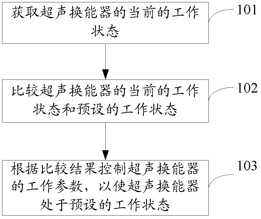
[0096] First, the circuit method is used to measure the working voltage and current of the ultrasonic transducer in real time, and the input signal of the ultrasonic transducer is detected by using the sample-hold circuit to obtain the envelope voltage and current value, and measure the voltage signal and current The phase difference of the signal, and then calculate the actual electric power value of the ultrasonic transducer according to the amplitude value of the voltage signal, the amplitude value of the current signal and the phase difference between the two.
[0097] Compare the actual electric power value with the preset output electric power value, adjust the output of the power amplifier circuit according to the difference (adjust the input signal amplitude or adjust the power amplifier gain. When the actual electric power value is less than the preset output electric power va...
Embodiment 2
[0098] Embodiment 2 Monitoring the voltage reflection standing wave ratio of the ultrasonic transducer
[0099] A radio frequency signal bidirectional power coupler is used to measure the forward and reverse radio frequency signals of the ultrasonic transducer to obtain its forward / reverse voltage signal, and calculate the voltage reflection standing wave ratio accordingly. According to the total output power of the ultrasonic transducer and the voltage reflection standing wave ratio, the values of the incident electric power and reflected electric power of the ultrasonic transducer can be calculated.
[0100] A too high voltage reflection standing wave ratio indicates that more electric power is reflected back to the output of the power amplifier, which may be due to the large difference between the real part of the electrical impedance of the ultrasonic transducer and the real part of the output impedance of the power amplifier (that is, too large Impedance mismatch), thus...
Embodiment 3
[0101] Embodiment 3 Monitoring the emission parameters of the ultrasonic transducer
[0102] First, the fundamental frequency is detected from the RF signal spectrum domain of the ultrasonic transducer, and the phase difference between the two is calculated from the measured voltage signal and current signal. If the phase difference between the voltage signal and the current signal at the fundamental frequency exceeds the preset difference range, it means that there may be a mismatch between the output of the power amplifier and the input impedance of the ultrasonic transducer, and the frequency of the output RF signal of the power amplifier needs to be adjusted Change the output impedance of the power amplifier, or change the output impedance matching network of the power amplifier to reduce the degree of impedance mismatch, correct the phase difference to the allowable difference range, and re-match the impedance at both ends to obtain the best electro-acoustic conversion eff...
PUM
 Abstract
Description
Claims
Application Information