
Device for continuously separating oil-water mixture collected from water surface

A technology of oil-water mixture and pumping device, which is applied in the direction of liquid separation, separation method, liquid separation auxiliary equipment, etc. It can solve the problems that have not been proposed, are rarely seen, and the oil-water separation device is difficult to match, and achieve high stability and reliability. Effect

Active Publication Date: 2013-04-10
黄海峰
View PDF12 Cites 11 Cited by
  • Summary
  • Abstract
  • Description
  • Claims
  • Application Information

AI Technical Summary

Problems solved by technology

However, it is rare to see a truly harmonious match with the oil slick collection device
[0008] Chinese patents (application numbers: 20102061379.1 and 200920015296.9) propose a method and device for oil-water separation, using vortex separation technology. From the actual operation, there is water in the oil, oil in the water, and the oil in the water is again Emulsification, its effect is not ideal
[0010] Chinese patent (application number: 94208190) proposes an oil-water separation method under negative pressure. This technology can keep the oil and water in their original form for separation. The oil-water mixture can be separated before the pump, avoiding the strong stirring and oil separation of the pump. Unfortunately, when using this method for continuous oil-water separation, how to automatically extract the stratified oil from the negative pressure and airtight state, the inventor did not propose effective and clear measures
[0011] With the emergence of a new oil slick collection device, the existing oil water separation device is more difficult to match

Method used


Image

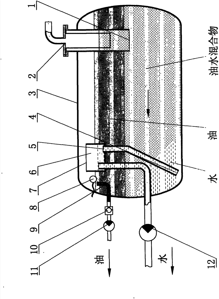
  • Device for continuously separating oil-water mixture collected from water surface
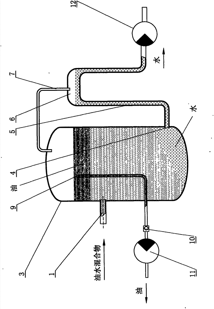
  • Device for continuously separating oil-water mixture collected from water surface
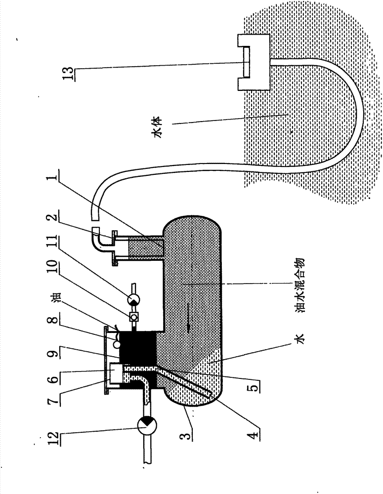
  • Device for continuously separating oil-water mixture collected from water surface

Examples


Embodiment Construction

[0045] 1. A device for continuous separation of oil-water mixture collected from water, as attached figure 1 Shown: a vertically placed filter 2 and a horizontally placed tank as a closed container 3; the water outlet end of the filter 2 is used as the oil-water mixture inlet 1 of the closed container, and a water outlet channel 5 is provided at the other end of the closed container 3 to discharge water The channel inlet 4 is located in the lower area of ​​the tank body; the water outlet channel 5 extends from the water outlet channel inlet 4 up to the upper space of the tank body and forms an upper open compartment as the overflow section 6, and the overflow section 6 connects with The upper space of the closed container 3 forms a pressure balance channel 7; the water outlet channel 5 opens in the overflow section 6, passes through the overflow section 6, and then connects with the pumping device 12 (self-priming water pump, water-air mixing pump, diaphragm Pumps, screw pumps, ...


PUM


Abstract

The invention discloses a device for continuously separating an oil-water mixture collected from a water surface. The device comprises a closed container, a water pumping device and an oil pumping device. The device is provided with an oil-water mixture inlet, a water outlet channel and an oil outlet channel in the closed container, wherein an inlet of the water outlet channel is positioned in a lower container space at the far end relative to the oil-water mixture inlet; the water outlet channel extends upwards to form an overflow zone at the height which corresponds to the upper space of the closed container and reaches to the water pumping device; the inlet of the oil outlet channel is formed in the upper container space; and the thickness of the oil layer is measured through the principle that the external and internal pressures in the overflow zone are equal, and when the oil layer reaches a certain thickness, the oil is pumped through the oil pumping device, the oil and water are rapidly separated in a negative pressure state, the emulsifying and stirring functions of the pump are avoided, the whole device is simple in structure, compact, high-efficiency, stable and reliable, the continuity is realized, and the automatic oil-water separation is realized.

Description

Technical field [0001] The invention belongs to the field of environmental protection and resource recovery equipment, and particularly relates to an oil-water separation equipment. Background technique [0002] There are many existing oil-water separation technologies and devices, such as membrane separation technology, vortex separation technology, coarse particle coalescence separation technology, air flotation separation technology and so on. [0003] The advantage of membrane separation technology is that it can finely separate the oil-water mixture, but the disadvantages of high cost, easy clogging, high liquid pressure, and difficult maintenance are also very obvious. [0004] The vortex separation technology can separate oil and water quickly and continuously. The structure is compact, but the separation accuracy is very rough. There is oil in the water and water in the oil. A powerful vortex often needs a higher flow rate to achieve, and it is usually achieved after the pump...

Claims


Application Information

Patent Timeline
IPC IPC(8): B01D17/025B01D17/12
Inventor 黄海峰
Owner 黄海峰
Learn More