
Brake device of electro-hydraulic brake system for vehicles

An electronic control, hydraulic braking technology, applied in the direction of braking transmission, braking action starting device, brake, etc., can solve the problems of driving the engine for a long time, reducing the combustion rate, etc., to achieve a simple structure, improve the combustion rate, ensure The effect of simplicity

Inactive Publication Date: 2013-04-10
HL MANDO CORP
View PDF9 Cites 6 Cited by
  • Summary
  • Abstract
  • Description
  • Claims
  • Application Information

AI Technical Summary

Problems solved by technology

[0005] In such a conventional vacuum brake, in order to form a vacuum, it is necessary to supply the suction pressure of the vehicle engine to the vacuum booster, and thus there is a problem that the combustion rate decreases.
In addition, there is a problem that the engine needs to be driven for a long time to create a vacuum when the vehicle is parked.
[0006] And, under the situation of above-mentioned fuel cell automobile and electronic automobile, because do not have engine, it is impossible to utilize the existing vacuum brake that amplifies driver's pedal force when braking, and under the situation of hybrid electric automobile, in order to improve combustion rate, Due to the idling stop function when parking, it is necessary to introduce hydraulic brakes

Method used


Image

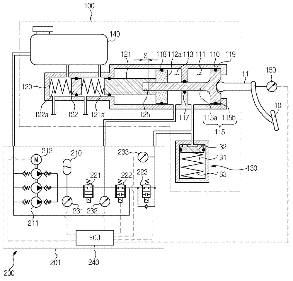
  • Brake device of electro-hydraulic brake system for vehicles
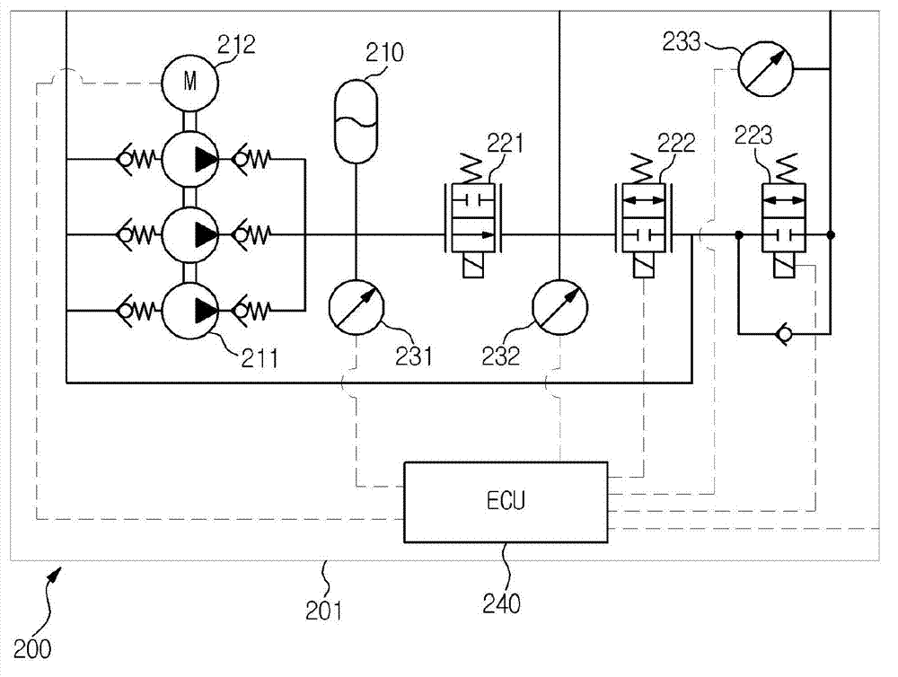
  • Brake device of electro-hydraulic brake system for vehicles
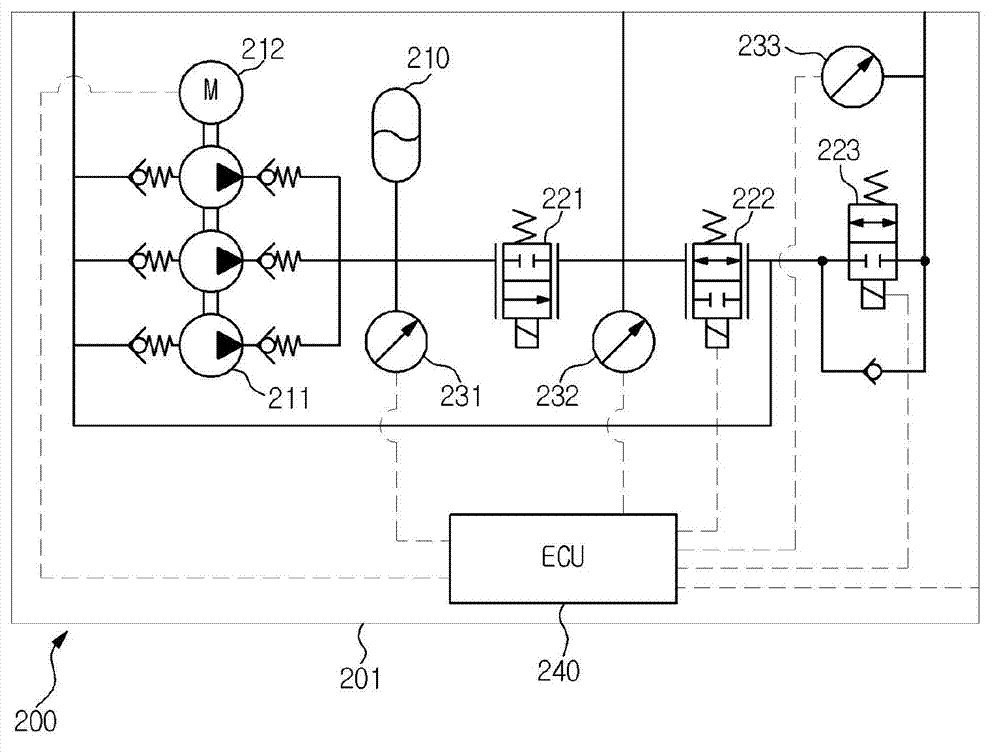
  • Brake device of electro-hydraulic brake system for vehicles

Examples


Embodiment Construction

[0049]Preferred embodiments of the present invention will be described in detail below with reference to the accompanying drawings. Prior to this, the interpretation of terms or words used in this specification and claims should not be limited to the meanings in ordinary dictionaries, but should be based on the inventor's ability to properly define the invention in the most precise way. principle, and interpret it as the meaning and concept that conform to the technical thought of the present invention. Therefore, the embodiment described in this specification and the structures shown in the drawings are only the most preferred embodiment of the present invention, and cannot represent the entire technical idea of ​​the present invention. It should be understood that when this application is filed, there may also be various equivalents and modified examples that can replace the content thereof.

[0050] The braking device of the electronically controlled hydraulic braking syst...


PUM


Abstract

Disclosed herein is a brake device of an electro-hydraulic brake system for vehicles which provides hydraulic braking force to transmit stable pedal feel and provides regenerative braking for fuel efficiency improvement. The brake device includes an actuator unit including a master cylinder, a housing including a boosting chamber and a simulation chamber, an input rod, a reservoir connected to the upper portion of the master cylinder and storing oil, a simulator connected to the simulation chamber and a pedal displacement sensor sensing displacement of the pedal, and a hydraulic control unit. The hydraulic control unit includes an accumulator, a pump sucking oil from the reservoir and discharging the oil to the accumulator, a motor, a first control valve, a second control valve, a third control valve, pressure sensors sensing the pressures of the accumulator, the boosting chamber and the simulation chamber, and an electronic control unit (ECU).

Description

technical field [0001] The present invention relates to a braking device for an electronically controlled hydraulic braking system for a vehicle, and in more detail, relates to a braking device for an electronically controlled hydraulic braking system for a vehicle, which provides hydraulic braking force while conveying a stable pedal feel , to provide regenerative braking for improved combustion rates. Background technique [0002] Recently, in order to increase combustion efficiency and reduce exhaust gas, development of hybrid vehicles, fuel cell vehicles, electric vehicles, etc. is actively being carried out. Such a vehicle must be provided with a braking device, that is, a braking device of a vehicle braking system. Here, the vehicle braking device means a device that can slow down or stop a traveling vehicle. [0003] A typical brake system for a vehicle includes a vacuum brake that generates a braking force using an engine suction pressure and a hydraulic brake that ...

Claims


Application Information

Patent Timeline
Patent Type & Authority Applications(China)
IPC IPC(8): B60T13/68B60T13/122B60T13/14
CPCB60T13/68B60T13/14B60T7/042B60T8/4077B60T13/142B60T1/10B60T8/17B60T8/32
Inventor 杨二镇黃涌晳丁炳厚
Owner HL MANDO CORP
Learn More