Tunnel drainage structure applicable to water-rich strata under unsymmetrical pressure and construction method thereof

A technology for tunnel drainage and water-rich strata, which is applied in the directions of drainage, earthwork drilling, safety devices, etc., can solve problems such as difficulty in effectively increasing the strength and stability of surrounding rock mass, difficulty in forming cementitious bodies, and inability to effectively eliminate them. Achieve the effect of improving cohesion and internal friction angle, increasing cohesion and internal friction angle, and preventing water leakage

Active Publication Date: 2013-04-10
HUNAN PROVINCIAL COMM PLANNING SURVEY & DESIGN INST CO LTD
View PDF6 Cites 21 Cited by
  • Summary
  • Abstract
  • Description
  • Claims
  • Application Information

AI Technical Summary

Problems solved by technology

The key of this method lies in the effect of grouting. For water-rich clay strata, sometimes the moisture in the soil cannot be effectively removed, making it difficult to form an effective cement between the grouting body and the soil particles, and it is difficult to effectively increase the grouting. The strength and stability of the large surrounding rock mass lead to safety accidents such as excessive deformation, landslides and roof fall during tunnel excavation

Method used


Image

  • Tunnel drainage structure applicable to water-rich strata under unsymmetrical pressure and construction method thereof
  • Tunnel drainage structure applicable to water-rich strata under unsymmetrical pressure and construction method thereof
  • Tunnel drainage structure applicable to water-rich strata under unsymmetrical pressure and construction method thereof

Examples


Embodiment 1

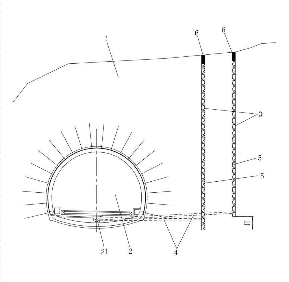
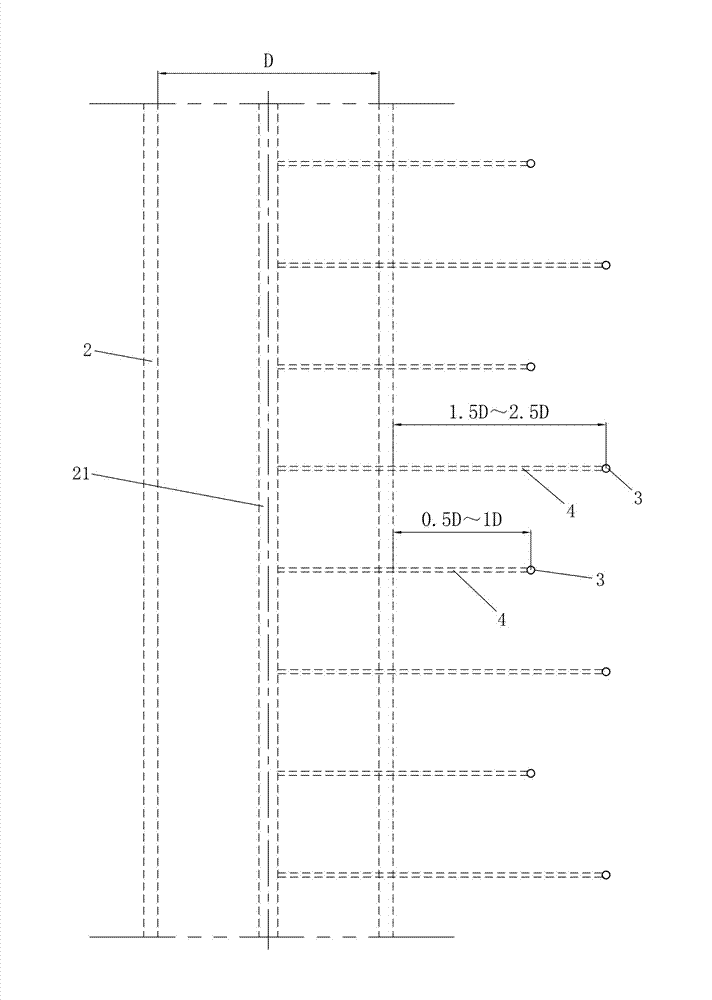
[0023] Such as figure 1 with figure 2 As shown, the present invention is applicable to the first embodiment of the tunnel drainage structure in the biased water-rich stratum. The tunnel drainage structure includes a tunnel body 2 located in the stratum 1, and an opening A plurality of vertical water collection wells 3 are dug, and a drainage channel 4 for draining water in the water collection wells 3 to the tunnel body 2 is provided between each water collection well 3 and the tunnel body 2 . By draining the water in the water collection well 3 for dewatering at the well point, the groundwater level of the formation 1 around the tunnel body 2 can be lowered, the cohesion and internal friction angle of the surrounding rock mass can be increased and improved, and the self-bearing capacity of the surrounding rock mass can be improved. capacity, during construction, before the excavation of the tunnel body 2, set up the water collection well 3, and then discharge the water in t...

Embodiment 2

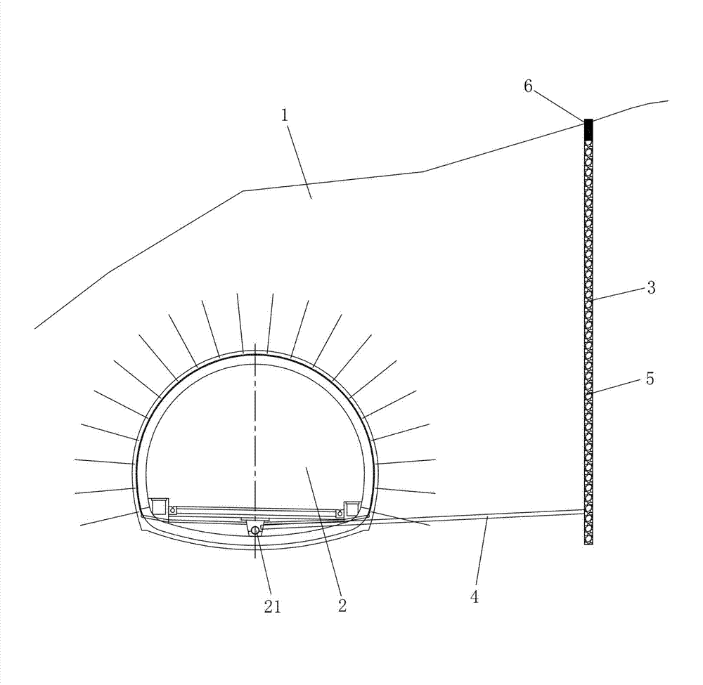
[0033] image 3 It shows the second embodiment of the tunnel drainage structure applicable to biased water-rich formations of the present invention. This embodiment is basically the same as Embodiment 1, except that the plurality of water collection wells 3 in this embodiment are only arranged in a row . The tunnel drainage structure of this embodiment is constructed with reference to the construction method of Embodiment 1.


PUM


Abstract

The invention discloses a tunnel drainage structure applicable to water-rich strata under unsymmetrical pressure and a construction method thereof. The tunnel drainage structure comprises a tunnel trunk located in a stratum, a plurality of water-collecting wells are dug in the stratum of the water-rich side of the tunnel trunk, and a drainage passage which is used for draining the water in the water-collecting well into the tunnel trunk is arranged between each water-collecting well and the tunnel trunk. The construction method of the tunnel drainage structure includes digging the water-collecting wells for well-point dewatering, digging the tunnel trunk, digging the drainage passages and other steps. The invention can decrease the water pressure around the tunnel, prevent water leakage during the operation of the tunnel and prevent landslides, tunnel face collapse and other accidents from taking place during construction, and has the advantages of high construction safety and the like.

Description

technical field [0001] The invention relates to the field of tunnel construction, in particular to a tunnel drainage structure suitable for biased water-rich formations and a construction method thereof. Background technique [0002] When the excavation of the tunnel body is carried out in the partial pressure water-rich stratum, when the surrounding rock mass is weak, especially in the fully-strongly weathered stratum, it is very easy to cause excessive convergence deformation in the tunnel, and even lead to landslide accidents , when the buried depth is not large, it is very easy to cause cracks on the surface of the mountain above the tunnel, and even landslides. When encountering such topographic bias and the geology is weak and water-rich, the conventional method generally adopts the cave roof to strengthen the mountain body with grouting, and at the same time adopts advanced grouting reinforcement and initial support in the cave to carry out excavation in sections . ...

Claims


Application Information

Patent Timeline
Patent Type & Authority Applications(China)
IPC IPC(8): E21F16/02
Inventor 邹金锋彭立蒋正华彭建国李亮张进华傅立新刘正刚王建华
Owner HUNAN PROVINCIAL COMM PLANNING SURVEY & DESIGN INST CO LTD
Why Eureka
Try Eureka