Energy-saving gas stove

A technology of gas stoves and gas, which is applied in household stoves, heating fuels, household stoves/stoves, etc. It can solve the problems of low heat utilization rate and achieve the effects of improving combustion quality, reducing emissions, and improving utilization rate

Inactive Publication Date: 2013-04-10
张金毅
View PDF6 Cites 5 Cited by
  • Summary
  • Abstract
  • Description
  • Claims
  • Application Information

AI Technical Summary

Problems solved by technology

[0002] At present, the known household gas stoves have the problem of low heat utilization rate. Heat loss mainly includes convection loss and radiation loss. Reducing heat loss and making full and effective use of heat energy can achieve the purpose of energy saving

Method used


Image

  • Energy-saving gas stove
  • Energy-saving gas stove
  • Energy-saving gas stove

Examples


specific Embodiment 1

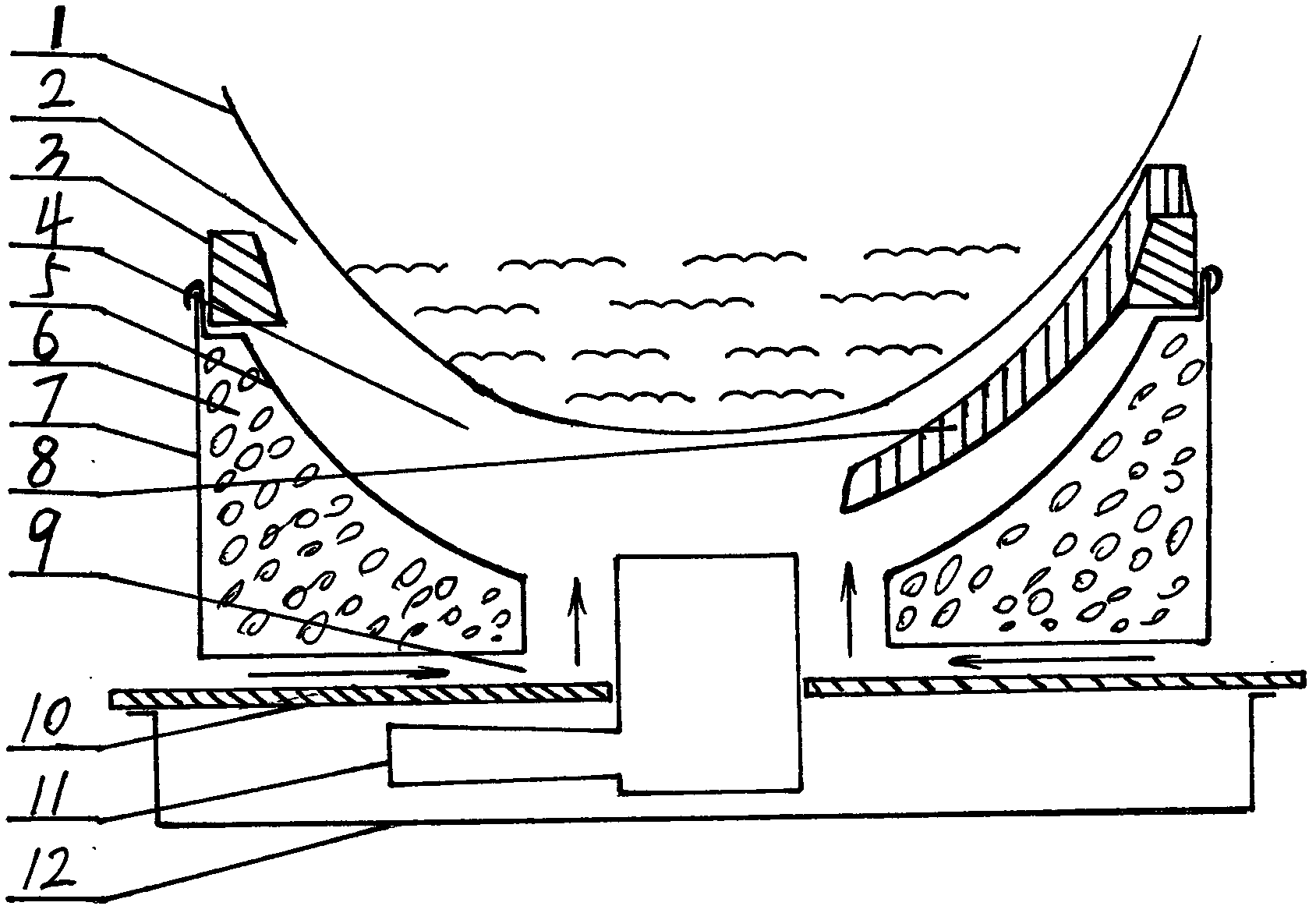
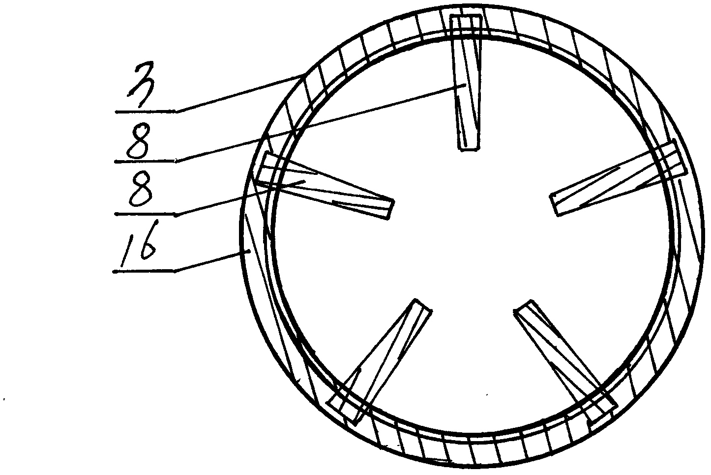
[0019] Specific embodiment one: as figure 1 As shown, the gas cooker of the present invention comprises: an energy-gathering and heat-insulating reflector 7, a burner 11, a cooker body panel 10, a combustion chamber 4, a stove frame A3, a gas control ring 22, and a bottom shell 12, and is characterized in that: the pot 1 , energy-gathering and heat-insulating reflector 7, burner head 11, burner rack A3, and gas control ring 22 together constitute combustion chamber 4, gas is ejected from burner head 11 for combustion, and the supplementary secondary air is provided by secondary supplementary air channel 9, air hole 23 enters the combustion-supporting gas, the combustion of the gas is carried out in the combustion chamber 4, and the flue gas after combustion is discharged from the flue gas outlet 2. In this new technology, the selection of pot 1 is required, specifically there are two points: one, the outer surface of pot 1 will all contact the inner side of the upper end of al...

specific Embodiment 2

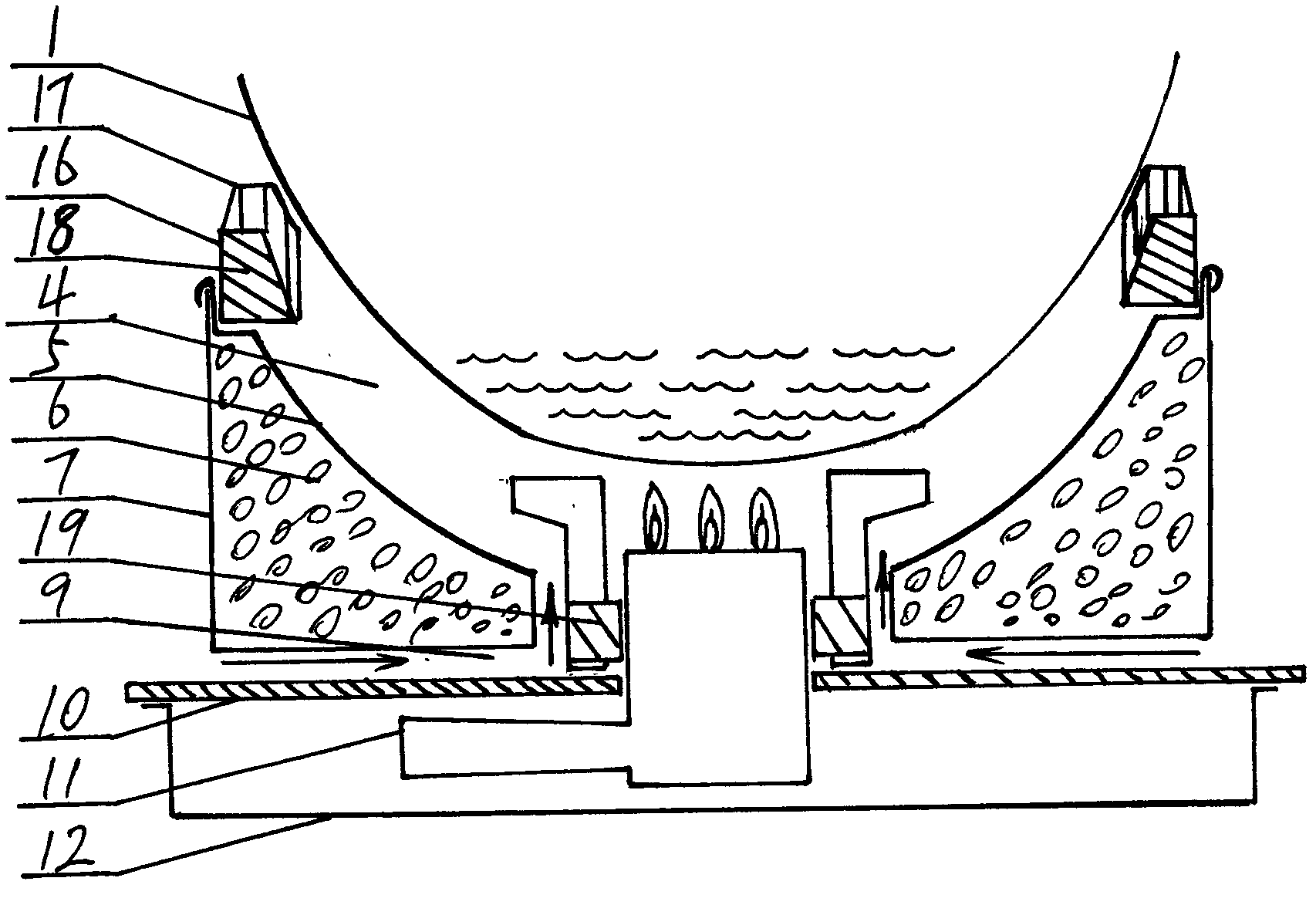
[0022] Specific embodiment two: as image 3 As shown, the gas stove of the present invention includes: energy-gathering heat-insulating reflector 7, burner head 11, stove body panel 10, combustion chamber 4, stove frame B18, support frame 19, bottom shell 12, described by pot 1, energy-gathering The heat-insulating reflector 7, the burner head 11, and the burner frame B18 together constitute the combustion chamber 4. Gas is ejected from the burner head 11 for combustion, and the supplementary secondary air enters the combustion-supporting channel 9 through the secondary supplementary air channel. The combustion of the gas is carried out in the combustion chamber 4. It is carried out inside, and the flue gas after combustion is discharged from the flue gas outlet 2. In this new technology, there are requirements for the selection of pot 1, specifically there are two points: one, the outer surface of pot 1 will all touch the inner side of the upper end of all support points 17 o...


PUM


Abstract

The invention relates to an energy-saving gas stove, which comprises an energy-gathering heat-insulation reflecting cover 7, a stove end 11, a stove body panel 10, a combustion cavity 4, a stove frame A3, a stove frame B18, a support frame 19, a gas control ring 22 and a bottom case 12. The energy-saving gas stove is characterized in that a pot 1, the energy-gathering heat-insulation reflecting cover 7, the stove end 11, the stove frame A3 or the stove frame B18 and the gas control ring 22 jointly form the combustion cavity 4, fuel gas is sprayed out from the stove end 11 for combustion, supplementary secondary air enters the combustion cavity 4 via a secondary supplementary air passage 9 and gas holes 23, the combustion of the fuel gas is carried out in the combustion cavity 4, and combusted smoke gas is exhausted from a smoke gas outlet 2 or a smoke gas outlet 13. The energy-gathering heat-insulation reflecting cover technology is adopted, the open external combustion type combustion of a domestic gas stove is changed into the semi-closed internal combustion type combustion, the heat radiation loss and the convection loss caused by the open state are reduced, the temperature in a combustion chamber is raised, the generation of harmful gas is reduced because of full combustion, the heat utilization rate is increased, the fuel gas consumption is saved, and the goals of energy protection and energy saving are reached.

Description

technical field [0001] The invention relates to a household gas stove. In particular, a high-efficiency and energy-saving household gas stove. technical background [0002] At present, the known household gas stoves have the problem of low heat utilization rate. The heat loss mainly includes convection loss and radiation loss. By reducing heat loss and fully and effectively utilizing heat energy, the purpose of energy saving can be achieved. Contents of the invention [0003] The object of the present invention is to provide a household gas stove, which can effectively and fully absorb and utilize heat energy, reduce heat loss, and achieve the purpose of energy saving and emission reduction. The invention is a new technology for changing the traditional way of using fire. This new technology changes the open fire to the closed fire, and changes the external combustion fire to the internal combustion fire, which can greatly improve the utilization rate of heat energy and ...

Claims


Application Information

Patent Timeline
Patent Type & Authority Applications(China)
IPC IPC(8): F24C3/08F24C15/20
CPCY02B40/00
Inventor 张伟生
Owner 张金毅
Why Eureka
Try Eureka