Two-dimensional airfoil type test platform

A test platform and airfoil technology, applied in aerodynamic tests, machine/structural component testing, measuring devices, etc., can solve problems such as complex design and difficulty in obtaining sufficiently accurate experimental data

Inactive Publication Date: 2013-04-10
中国航空工业空气动力研究院
View PDF4 Cites 21 Cited by
  • Summary
  • Abstract
  • Description
  • Claims
  • Application Information

AI Technical Summary

Problems solved by technology

The direct dynamometer method is a seemingly simple, but actually more complicated, experimental method for two-dimensional airfoils. If the parameters are not properly selected, it is often difficult to obtain sufficiently accurate experimental data compared with the first two methods, and the scheme design more complicated

Method used


Image

  • Two-dimensional airfoil type test platform
  • Two-dimensional airfoil type test platform
  • Two-dimensional airfoil type test platform

Examples


Embodiment 1

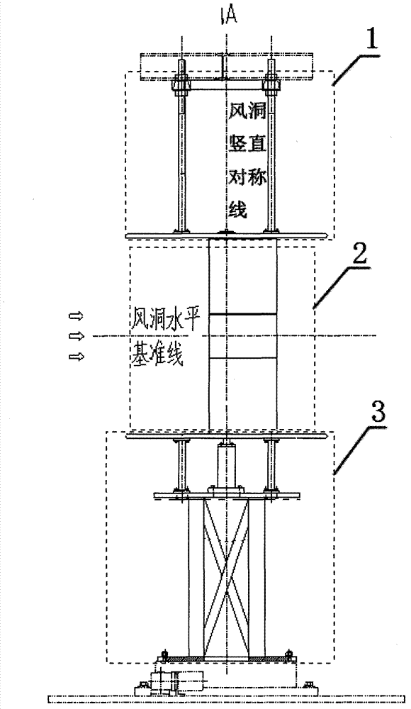
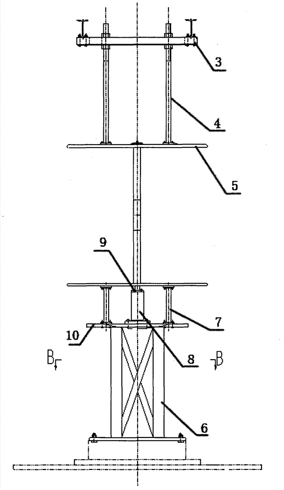
[0028] combine Figure 1-Figure 10 , a binary airfoil test platform, comprising an upper turntable unit 1, a lower turntable unit 3 and a test subject unit 2, the upper turntable unit 1 is connected to the test subject unit 2, the test subject unit 2 is connected to the lower turntable unit 3, and the upper turntable unit 1 It is connected with the I-beam on the upper floor of the wind tunnel, and the lower turntable unit 3 is connected with the turntable of the wind tunnel. The upper turntable unit includes an upper frame 3, a plurality of connecting rods 4 and an upper end plate 5, the upper frame 3 is fixed on the I-beam at the upper floor of the wind tunnel, and the upper frame 3 is fixedly connected with one end of a plurality of connecting rods 4 , the other ends of the plurality of connecting rods 4 are fixedly connected to the upper end plate 5 . The lower turntable unit includes a base 6, four support rods 7, a first support base 8, a second support base 9 and a lowe...

Embodiment 2

[0030] Using the turntable system of the wind tunnel, the model adopts the vertical installation method, adopts the NACA0015 airfoil, and the chord length is 250mm. In order to reduce the influence of the three-dimensional flow, the length of the measurement section is only 200mm, and the non-measurement section (following part) is symmetrically arranged in the measurement section. On both sides, plexiglass end plates (PMMA) are installed at both ends to eliminate the spanwise flow of the airfoil. The distance between the end plates is 800mm. The end plates are made of transparent materials for the convenience of flow observation. The non-measuring section of a certain length can avoid bringing the flow distortion of the end plate and the corner pocket of the airfoil to the measuring section. There is a gap of 0.5mm between the measuring section and the non-measuring section to prevent the two sections from colliding during deformation. At the same time, effective soft connect...

Embodiment 3

[0032] The lower turntable unit is installed on the lower turntable system of the wind tunnel, and the upper turntable unit is fixed on the beam at the upper part of the test section. The upper and lower turntable units are connected by a three-section shaft, the airfoil is equipped with a central shaft, the lower part of the lower shaft is connected with the lower turntable, and the upper part of the upper shaft is connected with the upper turntable unit through self-aligning bearings, so that it can ensure When the rotation of the wind tunnel turntable drives the lower turntable unit of the mechanism to rotate, the upper turntable unit does not move, and the airfoil rotates with the rotation of the lower turntable. The advantage of this is that there are no redundant structures such as beams and columns around the airfoil flow field to affect the flow field, which will greatly facilitate the measurement of the airfoil wake. The airfoil is molded with high compressive non-met...


PUM


Abstract

The invention relates to a two-dimensional airfoil type test platform comprising an upper turnplate unit (1), a lower turnplate unit (3) and a test theme unit (2), the turnplate unit (1) is connected with the test theme unit (2), the test theme unit (2) is connected with the lower turnplate unit (3), the turnplate unit (1) is connected with an H-shaped beam in the floor position on the wind tunnel, and the lower turnplate unit (3) is connected with a wind tunnel turnplate. The two-dimensional airfoil type test platform has the advantages that the weight of a model is independent of a resistance component, a variation range in load of the resistance component along the axon is not big, and relatively small resistance changes are easy to measure. Another advantage is that an outlaid balance is not prone to being affected by high-voltage high-frequency discharge of an electrode on the model surface.

Description

technical field [0001] The invention relates to wind tunnel test technology, specifically a binary airfoil test platform. Background technique [0002] At present, there are three main methods for binary airfoil experiments in wind tunnels: airfoil surface pressure measurement method, momentum method and direct force measurement method. The direct dynamometer method is a seemingly simple, but actually more complicated, experimental method for two-dimensional airfoils. If the parameters are not properly selected, it is often difficult to obtain sufficiently accurate experimental data compared with the first two methods, and the scheme design more complicated. However, since the airfoil aerodynamic force of this method is directly measured by the balance, the experimental results are directly clear, and it is very economical, so it still has certain applications in some subject research and type tests. Contents of the invention [0003] The purpose of the present invention...

Claims


Application Information

Patent Timeline
Patent Type & Authority Applications(China)
IPC IPC(8): G01M9/06
Inventor 由亮张国友王铭威牛中国
Owner 中国航空工业空气动力研究院
Why Eureka
Try Eureka