Reaction device for pyrolyzing chemical raw materials by adopting steam

A technology for chemical raw materials and reaction devices, applied in pressure vessels, heat treatment, chemical instruments and methods used in chemical processes, etc., can solve problems such as adverse effects of experimental product analysis, inability to form biomass carbon preparation, and reducing the accuracy of experimental results. , to achieve the effect of shortening the cooling time, strengthening the heat exchange, and enhancing the cooling effect

Active Publication Date: 2017-05-31
HEFEI UNIV OF TECH
View PDF3 Cites 3 Cited by
  • Summary
  • Abstract
  • Description
  • Claims
  • Application Information

AI Technical Summary

Problems solved by technology

Existing traditional reaction devices that use hydrothermolysis of chemical raw materials often place materials directly in water when performing pyrolysis experiments. During the reaction process, some substances in the materials dissolve in water, which adversely affects the analysis of experimental products. , reducing the accuracy of the experimental results; at the same time, there are disadvantages that the material cannot be kept in shape (for example, the preparation of shaped biochar cannot be carried out); in addition, the existing traditional reaction device using hydrothermolysis chemical raw materials lacks a cooling system, resulting in cooling time It is too long, and at the same time, the waste heat will have a certain impact on the reaction product

Method used


Image

  • Reaction device for pyrolyzing chemical raw materials by adopting steam
  • Reaction device for pyrolyzing chemical raw materials by adopting steam
  • Reaction device for pyrolyzing chemical raw materials by adopting steam

Examples


Embodiment 1

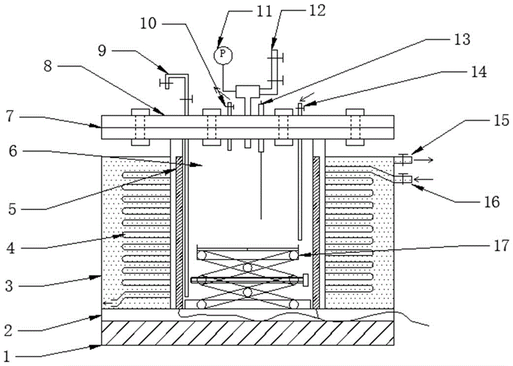
[0032] see figure 1 , a reaction device using steam pyrolysis of chemical raw materials includes a cylindrical cavity 6, the outside of the cavity 6 is sequentially fitted with a heating mechanism 2 and a cooling mechanism; the top of the cavity 6 is provided with an everted flange 7 , The flange side 7 and the top cover 8 are sealed and connected by a gasket. The top cover 8 is equipped with an exhaust pipe 10, an air intake pipe 14, a liquid sampler 9 and a safety unloading valve 12 connected to the inside of the cavity 6, an exhaust valve is installed on the exhaust pipe 10, and an inlet valve is installed on the air intake pipe 14. Air valve; sampler 9 includes a sampling tube, the lower part of the sampling tube is located in the cavity 6, and a sampling valve is installed on the top of the sampling tube. A pressure gauge 11 and a temperature sensor 13 are also installed on the top cover 8 . The inside of the cavity 6 is equipped with a loading bracket 17; see figure ...

Embodiment 2

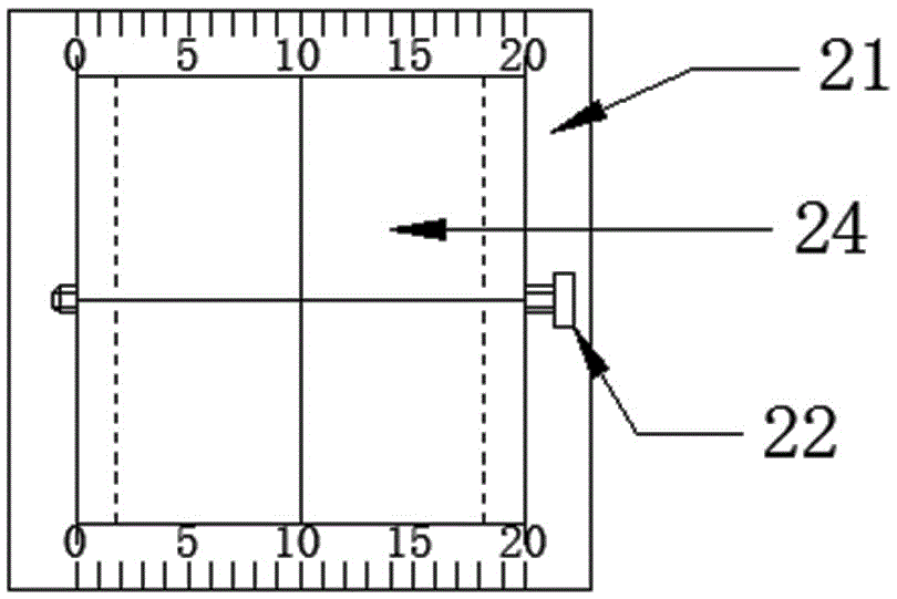
[0039] see image 3 , The loading tray 24 is divided into four small plates, which can realize simultaneous pyrolysis reactions on four different substances.


PUM


Abstract

The invention relates to a reaction device for pyrolyzing chemical raw materials by adopting steam. The device comprises a cavity, a heating mechanism, a cooling mechanism and a top cover of the cavity, wherein the heating mechanism and the cooling mechanism are sequentially arranged outside the cavity; an object carrying support is arranged inside the cavity; an exhaust pipe, an air inlet pipe, a liquid sampler and a safety unloading valve which are communicated with the inner part of the cavity are arranged on the top cover; during use, water is added into the cavity, and the water surface is positioned at the lower-middle part of the object carrying object; a pyrolyzed substance is arranged on the object carrying object; the cavity is sealed, and the heating mechanism is started, so that the water in the cavity is uniformly heated to generate water vapor with high temperature and high pressure, and the pyrolyzed substance generates a pyrolytic reaction; the pyrolytic reaction stops and inert gases are introduced into the cavity, so that the water vapor in the cavity is exhausted through the exhaust pipe; when the inner part of the cavity is filled with the inert gases, the cooling mechanism is opened; when the cavity is cooled to room temperature, the reaction is finished. According to the reaction device disclosed by the invention, direct contact between the raw materials and the water is avoided, and the aim of preserving the shape of reaction materials is achieved; the accuracy of an experimental result is improved.

Description

technical field [0001] The invention belongs to the technical field of chemical equipment, and in particular relates to a reaction device for pyrolyzing chemical raw materials with steam. Background technique [0002] The reaction device using hydropyrolysis of chemical raw materials is one of the commonly used equipment in the laboratory. It is often used to complete the pyrolysis reaction of materials such as biomass, titanium dioxide, cement and fly ash. Existing traditional reaction devices that use hydrothermolysis of chemical raw materials often place materials directly in water when performing pyrolysis experiments. During the reaction process, some substances in the materials dissolve in water, which adversely affects the analysis of experimental products. , reducing the accuracy of the experimental results; at the same time, there are disadvantages that the material cannot be kept in shape (for example, the preparation of shaped biochar cannot be carried out); in ad...

Claims


Application Information

Patent Timeline
Patent Type & Authority Applications(China)
IPC IPC(8): B01J6/00B01J3/04
Inventor 张贤文付一轩邢勇强
Owner HEFEI UNIV OF TECH
Why Eureka
Try Eureka