
Parallel magnetic resonance imaging device and imaging method thereof

A magnetic resonance imaging and imaging channel technology, applied in the medical field, can solve the problems of large loss of image-to-noise ratio, inaccurate estimation, large artifacts, etc., to achieve the effect of improving imaging speed and small loss of signal-to-noise ratio

Active Publication Date: 2015-09-23
SHENZHEN INST OF ADVANCED TECH CHINESE ACAD OF SCI
View PDF2 Cites 1 Cited by
  • Summary
  • Abstract
  • Description
  • Claims
  • Application Information

AI Technical Summary

Problems solved by technology

We divide this combination method into three categories: one is L1 norm-limited reconstruction using the coil sensitivity map as prior information, such as sparseSENSE, in sparseSENSE, the coil sensitivity value is the same as the traditional Sense reconstruction, first put The sensitivity matrix is ​​obtained by using under-sampled data or separated pre-scan data, and then combined with CS sparse constraints to reconstruct the image. However, this method, like the traditional Sense, still has a large Artifacts
The second is to add CS sparse constraints in GRAPPA. This method is to use the prior collection data to obtain some weight values ​​to estimate the uncollected data. However, it is not very accurate to use the intermediate full collection data to estimate the edge uncollected data. estimated
The third is like sparseSENSE, except that the image and the sensitivity matrix are reconstructed at the same time. According to the different prior constraints, this class can be divided into many methods. In the reconstruction formula, some use the sparsity of the final image as a priori Constraints, some use coil sensitivity smoothness or sparsity as prior constraints, but the loss of image-to-noise ratio is large

Method used

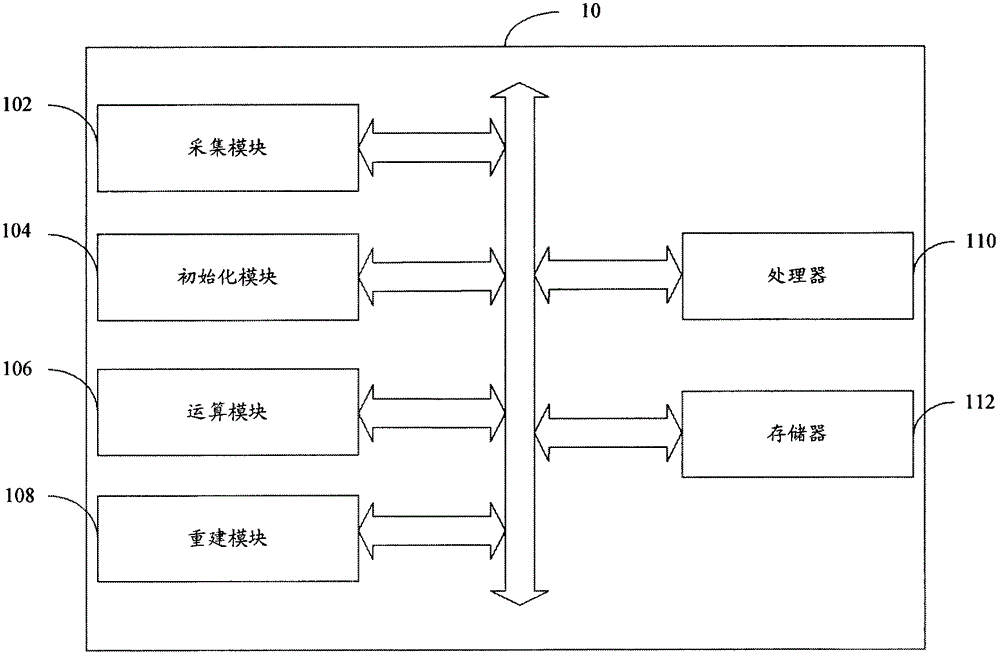
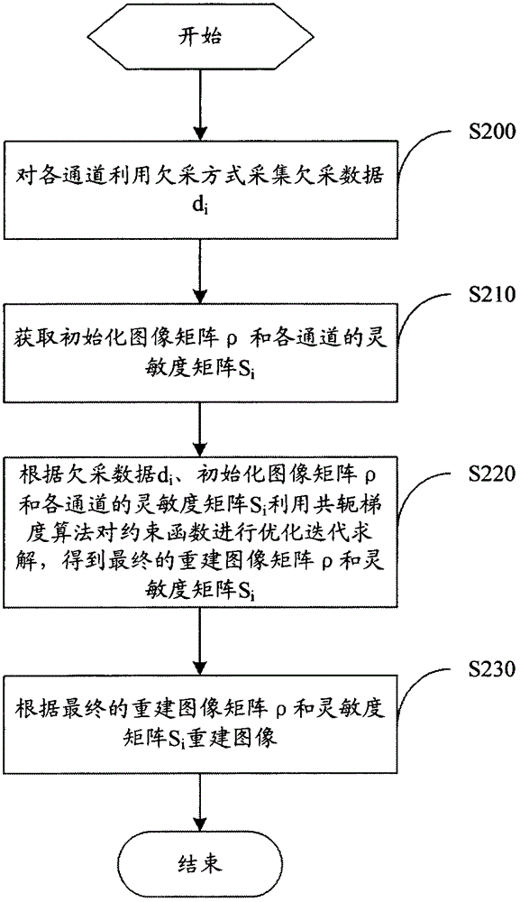

Image

  • Parallel magnetic resonance imaging device and imaging method thereof
  • Parallel magnetic resonance imaging device and imaging method thereof
  • Parallel magnetic resonance imaging device and imaging method thereof

Examples


Embodiment Construction

[0014] Embodiments of the present invention are described in detail below, examples of which are shown in the drawings, wherein the same or similar reference numerals designate the same or similar elements or elements having the same or similar functions throughout. The embodiments described below by referring to the figures are exemplary only for explaining the present invention and should not be construed as limiting the present invention.

[0015] In the description of the present invention, the orientation or positional relationship indicated by the terms "inner", "outer", "longitudinal", "transverse", "upper", "lower", "top", "bottom" etc. are based on the drawings The orientations or positional relationships shown are only for the convenience of describing the invention and do not require the invention to be constructed and operated in a specific orientation, and thus should not be construed as limitations on the invention.

[0016] see figure 1 , figure 1 Shown is a b...


PUM


Abstract

A parallel magnetic resonance imaging device comprises a plurality of imaging channels, a collection module, an initialization module, an operation module and a reconstruction module, wherein the collection module is used for collecting an undersampling matrix di (i is the serial number of each imaging channel and i > 0) from the plurality of imaging channels in an undersampling method and according to undersampling factors, the initialization module is used for acquiring an initialization image matrix rho and an initialization sensitivity matrix si (i is the serial number of each imaging channel and i > 0) of the imaging channels, the operation module is used for optimization iteration solving of a constraint function by means of the conjugate gradient algorithm according to the undersampling matrix di, the initialization image matrix rho and the initialization sensitivity matrix si to obtain a reconstructed image matrix rho and a sensitivity matrix si, and the reconstruction module is used for reconstructing an image according to the reconstructed image matrix rho and the sensitivity matrix si. When the parallel magnetic resonance imaging device is used for image reconstruction, imaging speed is effectively increased, and signal to noise ratio loss is small.

Description

technical field [0001] The invention relates to medical technology, in particular to a parallel magnetic resonance imaging device and an imaging method thereof. Background technique [0002] MRI has become one of the important means of clinical medical examination, providing very valuable diagnostic information for clinical medicine. Compared with other medical imaging technologies, MRI technology has the advantages of no radiation hazard, multi-directional and multi-parameter imaging, etc. It is very sensitive to the examination of soft tissues, and can not only display the morphological information of human anatomical structures, but also reflect certain aspects of human tissues. Some physiological and biochemical information. However, the imaging speed of MRI is slow, and the physiological movement of the subject's body during the imaging process will blur the image and distort the contrast, which cannot meet the requirements of rapid imaging such as cardiac dynamic imag...

Claims


Application Information

Patent Timeline
Patent Type & Authority Patents(China)
IPC IPC(8): G01R33/56
Inventor 史彩云谢国喜邱本胜刘新宋一彪
Owner SHENZHEN INST OF ADVANCED TECH CHINESE ACAD OF SCI
Learn More