Passive single pixel telescope imaging system and imaging method

A technology of imaging system and imaging method, which is applied in the parts of TV system, image communication, TV, etc., can solve the problems of difficult signal detection, short measurement time, long measurement time, etc., so as to improve the detection signal ratio and image reconstruction speed Fast, anti-interference enhanced effect

Inactive Publication Date: 2016-01-06
ZHENGZHOU UNIV
View PDF8 Cites 15 Cited by
  • Summary
  • Abstract
  • Description
  • Claims
  • Application Information

AI Technical Summary

Problems solved by technology

[0005] Although the above methods can use a single-pixel detector to obtain the image of the target object through a certain number of light field measurements, they all have certain shortcomings: (1) Quantum imaging uses the correlation of entangled photons for imaging, which has strong anti- Interference, but scanning is required, and the measurement time is extremely long; (2) Compressed sensing single-pixel imaging uses the sparsity of the image, and the measurement time is relatively short, but the algorithm solution process is very complicated; (3) Based on Fourier spectrum The biggest advantage of sampling single-pixel imaging is that the algorithm is very simple, only inverse Fourier transform, but the existing technology needs to project cosine structured light onto the target object, reflect the object and collect light intensity for imaging
The Fourier spectral sampling single-pixel imaging method has the best imaging quality for nearby objects, but for distant targets (50m~several kilometers), it is difficult to project cosine fringes. First, the fringe distortion caused by atmospheric disturbance destroys the theoretical The completeness of the fringe pattern in the derivation; the second is that the light diverges during the projection process, the light reaches the target surface, diverges again after being reflected by the object, and it is difficult to detect the signal that reaches the detector covering the spectrum change; Need to focus precisely on the target, which is especially difficult for small objects; Fourth, for long-distance transmission, the contrast will decrease with the increase of distance, and finally the fringe signal will be submerged in noise

Method used


Image

  • Passive single pixel telescope imaging system and imaging method
  • Passive single pixel telescope imaging system and imaging method
  • Passive single pixel telescope imaging system and imaging method

Examples


Embodiment 1

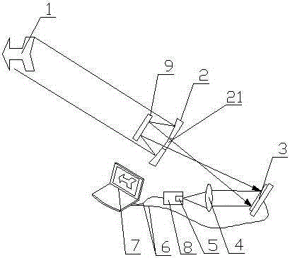
[0030] A passive single-pixel telephoto imaging system, its structure is as follows figure 1 As shown, it includes an imaging lens, a digital micromirror array (DMD) 3, a beam converging lens 4 and a data acquisition card 8 arranged sequentially on the optical path; the digital micromirror array (DMD) 3 is arranged at the imaging position of the imaging lens, and the beam converge The lens 4 is located on the optical path of the output light of the digital micromirror array (DMD) 3; the data acquisition card 8 is provided with a photoelectric conversion chip 5, and the data acquisition card 8 and the digital micromirror array (DMD) 3 communicate with the processor through the data line 6 connect.

[0031] The chip pixel number of the digital micromirror array (DMD) 3 is 1024×768pixels, and the pixel size is 13.68×13.68 microns.

[0032] The imaging lens includes a coaxial primary mirror 2 and a secondary mirror 9, the primary mirror 2 is close to the digital micromirror array...

Embodiment 2

[0042] A single-pixel camera telephoto imaging system, the difference from Embodiment 1 is: a liquid crystal spatial light modulator for amplitude modulation transmission is arranged between the imaging lens and the beam converging lens 4 along the optical path.

[0043] The difference between the imaging method implemented by the above imaging system and the embodiment 1 is that the modulated image in step (3) is transmitted by the liquid crystal spatial light modulator and hits the beam converging lens 4 .


PUM


Abstract

The invention discloses a passive single pixel telescope imaging system, and belongs to an optical imaging field. The passive single pixel telescope imaging system comprises an imaging lens, a spatial light modulator, a light beam convergent lens and a data acquisition card, which are orderly arranged on a light path; the spatial light modulator is arranged at an imaging position of the imaging lens; the light beam convergent lens is located on a light path of an output beam of the spatial light modulator; the data acquisition card is provided with a photovoltaic conversion chip; the data acquisition card and the spatial light modulator are connected with a processor through a data line. The imaging system is simple in structure and low in environmental requirement; besides, the acquisition time can be effectively reduced and the recovery of target images under a low sampling rate can be realized. The invention further discloses a passive single pixel telescope imaging method. The imaging method is simple in recovery algorithm and fast in image reconstruction speed, and can shoot and reconstruct the images of large sizes, so that the imaging method has a higher application value in the macro fields like military, remote sensing satellite, astronomy and engineering detection, etc.

Description

technical field [0001] The invention belongs to the field of optical imaging, and in particular relates to a passive single-pixel telescopic imaging system and a corresponding passive single-pixel telescopic imaging method. Background technique [0002] With the development of photosensitive sensors such as high-pixel CCD and CMOS, the spatial resolution of optical imaging is getting higher and higher, and the image quality is getting finer and finer. However, the pixel improvement of the image sensor has begun to be limited by the process. Higher pixels bring about a sharp reduction in the size of a single pixel, resulting in unfavorable factors such as a reduction in the photosensitive surface and increased noise. At the same time, higher pixels require a higher-performance image engine. Bringing higher power consumption also directly increases the complexity of the hardware and pushes up the cost of the imaging system. [0003] For non-visible light bands, especially inf...

Claims


Application Information

Patent Timeline
Patent Type & Authority Applications(China)
IPC IPC(8): H04N5/225H04N5/232
Inventor 田勇志韩建辉梁二军
Owner ZHENGZHOU UNIV
Why Eureka
Try Eureka