
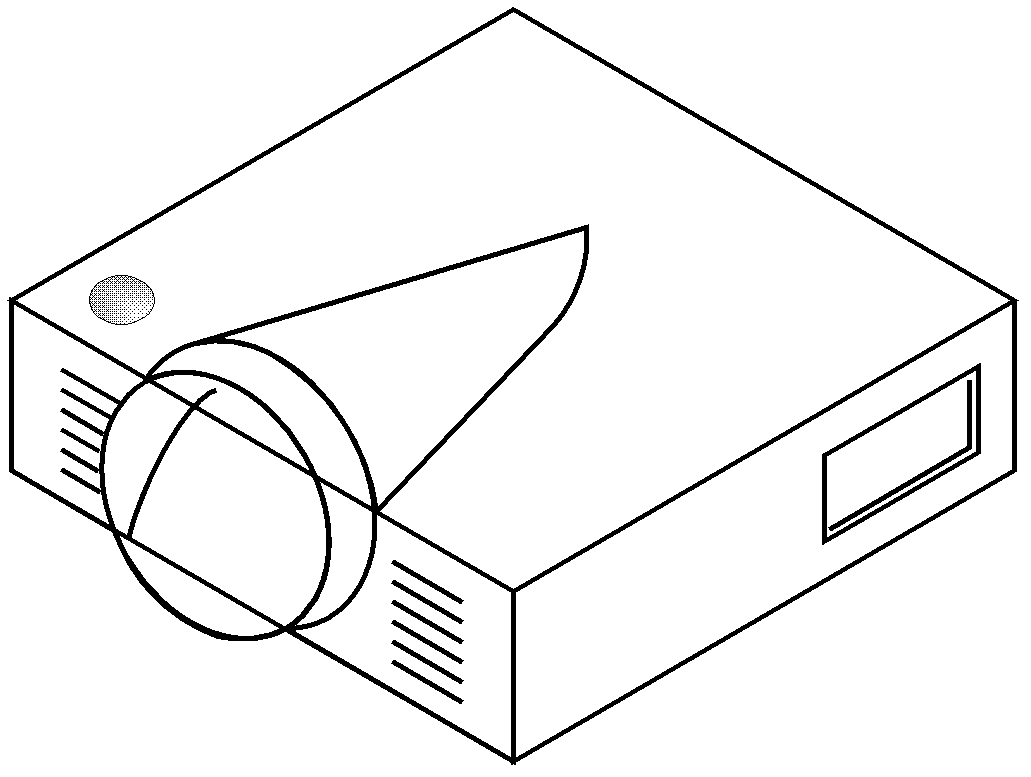
Projector

A technology of projectors and metamaterials, which is applied in the direction of instruments, projection devices, antennas, etc., to reduce costs and meet the effect of miniaturization

Active Publication Date: 2013-04-10
KUANG CHI INST OF ADVANCED TECH +1
View PDF5 Cites 10 Cited by
  • Summary
  • Abstract
  • Description
  • Claims
  • Application Information

AI Technical Summary

Problems solved by technology

However, important indicators such as the size, bandwidth, and gain of the antenna are limited by basic physical principles (gain limit, bandwidth limit, etc. under a fixed size)
The basic principle of the limit of these indicators makes the technical difficulty of the built-in antenna far more than that of other devices, and due to the complexity of the electromagnetic field analysis of radio frequency devices, approaching these limit values ​​has become a huge technical challenge

Method used


Image

  • Projector
  • Projector
  • Projector

Examples


no. 1 approach

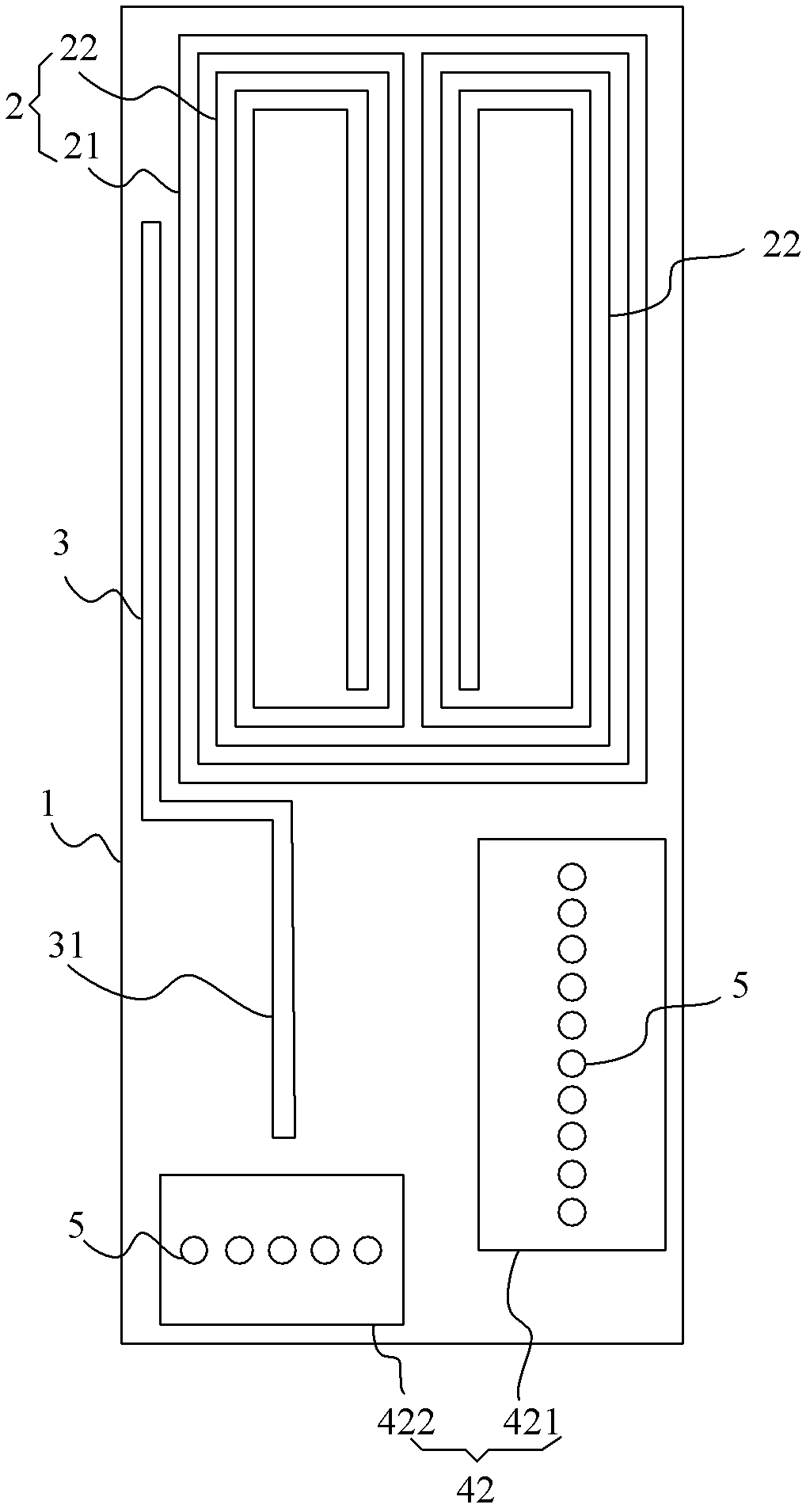
[0033] Please also refer to image 3 and Figure 4 , the metamaterial antenna 10 includes a dielectric substrate 1, a metal structure 2, a feeder 3, and reference grounds 41, 42. The dielectric substrate 1 is in the shape of a rectangular plate, and it can be made of polymers, ceramics, ferroelectric materials, and ferrite materials. Or ferromagnetic materials and other materials. In this embodiment, the material of the dielectric substrate 1 is made of glass fiber material (FR4), so that not only the cost is low, but also good antenna working characteristics can be maintained at different working frequencies.

[0034] The metal structure 2 , the feeder 3 and the reference grounds 41 and 42 are respectively placed on the two opposite surfaces of the dielectric substrate 1 , the metal structure 2 , the feeder 3 and the reference grounds 41 and 42 are formed with the dielectric substrate 1 Metamaterial antenna, the performance of the metamaterial antenna depends on the metal s...

no. 2 approach

[0042] Such as Figure 6 As shown, it is a schematic structural diagram of a metamaterial antenna 10 according to an embodiment of the present invention. The metamaterial antenna 10 in this embodiment includes a dielectric substrate 7 , a feeding point 5 arranged on the dielectric substrate 7 , a feeding line 4 connected to the feeding point 5 , and a planar metal structure 6 . Among them, the feeder 4 and the metal structure 6 are coupled to each other; the metal structure 6 is formed by engraving a slot topology 61 on a metal sheet, and the material corresponding to the slot topology 61 is removed during engraving, and the remaining metal sheet is the metal structure 6. After exiting the topological structure 61 of the slot, metal traces 62 included in the metal structure 6 appear on the metal sheet; the distance between adjacent slots in the topological slot structure 61 is the width of the traces 62, and the width of the topological structure 61 is the same as The widths ...


PUM


Abstract

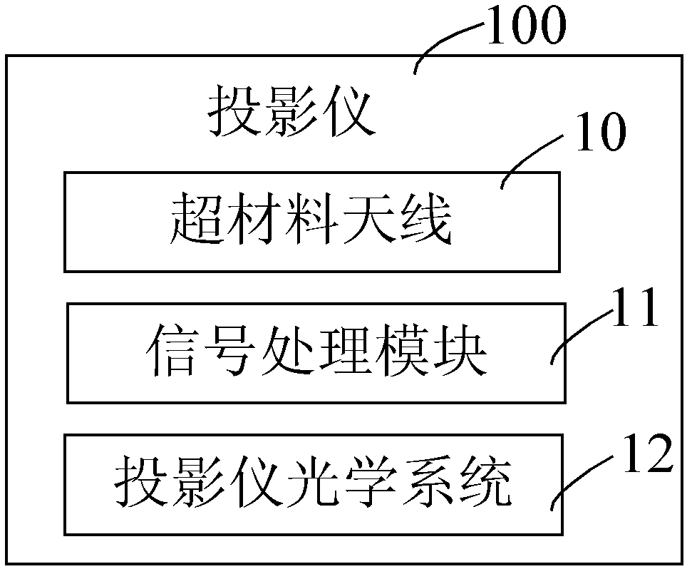
A projector comprises a metamaterial antenna, a signal processing module and a projector optical system. The metamaterial antenna comprises a dielectric substrate, a feeding point which is arranged on the surface of the metamaterial antenna, a feeder liner which is connected with the feeding point and a metal structure. The feeder liner and the metal structure coupling with each other; the metamaterial antenna receives electromagnetic wave signals containing video and audio information, then switches the electromagnetic wave signals into electrical signals; the signal processing module is used for processing the electrical signals and generating result information; and the projector optical system responds to the result information and projects into images. The projector utilizes the built-in metamaterial antenna to transmit high speed, ultra wide band and high capacity video and audio information to the projector wirelessly and reduces the cost caused by installing different kinds of data interfaces greatly.

Description

technical field [0001] The invention relates to projector equipment, in particular to a projector for wireless video and audio access. Background technique [0002] With the development of various projector technologies, projectors are widely used in various video output display devices. With the various requirements of video transmission, the projector equipment is equipped with various specifications of video and audio input interfaces, such as VGA input interface, USB interface, DVI interface, HDMI interface, RS232 interface and other video and audio input interfaces. Therefore, it is necessary to include various interface data cables in the projector setting accessories, and it is necessary to use wired methods to transmit video and audio signals from various signal sources to the projector. In particular, you can carry a projector with you, also known as a mini projector or a pocket projector. When using these portable projectors, every time a video and audio source (...

Claims


Application Information

Patent Timeline
IPC IPC(8): H01Q1/24H01Q1/36H01Q1/38H01Q1/48H01Q5/01G03B21/00H01Q5/10
Inventor 刘若鹏徐冠雄
Owner KUANG CHI INST OF ADVANCED TECH
Learn More