Cross head for cross head diesel engine

A crosshead type, diesel engine technology, applied in the crosshead field, can solve problems such as surface pressure rise, cost increase, lubricating oil film rupture, etc., and achieve the effect of reducing thickening and lightening cost

Active Publication Date: 2013-04-10
MITSUBISHI HEAVY IND LTD +1
View PDF7 Cites 4 Cited by
  • Summary
  • Abstract
  • Description
  • Claims
  • Application Information

AI Technical Summary

Problems solved by technology

[0006] However, if the strength of the slide plate is increased to suppress deformation of the slide plate, not only will the cost increase, but also the surface pressure between the slide plate and the crosshead will increase, and there may be problems such as cracking of the lubricating oil film.

Method used


Image

  • Cross head for cross head diesel engine
  • Cross head for cross head diesel engine
  • Cross head for cross head diesel engine

Examples


Embodiment Construction

[0055] Hereinafter, an embodiment of the present invention will be described with reference to the drawings.

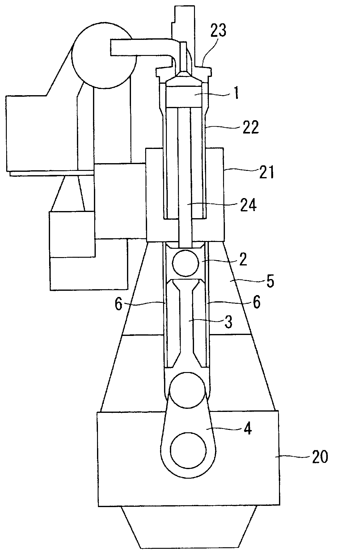
[0056] figure 1 A schematic configuration of a crosshead diesel engine according to an embodiment of the present invention is shown. The diesel engine shown in this figure is mainly used as the main engine for ship propulsion, and it is a two-stroke one-working cycle DC scavenging method.

[0057] This diesel engine has: a frame 20 located below; a frame (main body) 5 provided on the frame 20 ; and a cylinder block 21 provided on the frame 5 . The machine base 20, the machine frame 5, and the cylinder body 21 are fastened and fixed integrally by a plurality of tension bolts (not shown) extending in the vertical direction.

[0058]A cylinder liner 22 is provided on the cylinder block 21 , and a cylinder head 23 is provided at the upper end of the cylinder liner 22 . A reciprocating piston 1 is provided in a space formed by the cylinder liner 22 and the cylinder head...


PUM


Abstract

The purpose of the present invention is to provide a cross head for a cross head diesel engine, the cross head being configured so that the surface pressure between slide plates and the cross head can be reduced without increasing the strength of the slide plates. A cross head (2) for a cross head diesel engine, comprising: a pin (14) for rotatably connecting one end of the piston rod and one end of the connecting rod; shoes (8) reciprocating and sliding on the slide plates raised from the fixed end of the slide plates, which are affixed to a framework, toward the free ends of the slide plates; and connecting plates (13) for connecting the pin (14) and the shoes (8). End sections (8c, 8d) of each of the shoes (8) in the reciprocation direction are thin sections (8f) having a smaller thickness than the center section (8e) of the shoe (8).

Description

technical field [0001] The invention relates to a crosshead of a crosshead diesel engine. Background technique [0002] Conventionally, a crosshead type diesel engine has been used as a main engine for ship propulsion (see Patent Document 1). This type of crosshead diesel engine has a crosshead that rotatably connects one end of a piston rod and one end of a connecting rod, and reciprocates while sliding on a slide plate fixed to the main body. As the crosshead reciprocates on the sliding plate, force is transmitted from the piston to the crosshead through the piston rod. The component of this transmitted force in the lateral direction (direction toward the slide plate) is called lateral force, which is the force that deforms the slide plate. [0003] In order to suppress the deformation of the sliding plate, conventionally, the strength of the sliding plate has been increased by increasing the thickness of the sliding plate or providing additional ribs for suppressing the...

Claims


Application Information

Patent Timeline
Patent Type & Authority Applications(China)
IPC IPC(8): F02B75/32F16C5/00
CPCF16C5/00F02B75/32
Inventor 门胁刚国弘信幸
Owner MITSUBISHI HEAVY IND LTD
Why Eureka
Try Eureka