This helps you quickly interpret patents by identifying the three key elements:
Problems solved by technology
Method used
Benefits of technology
Problems solved by technology
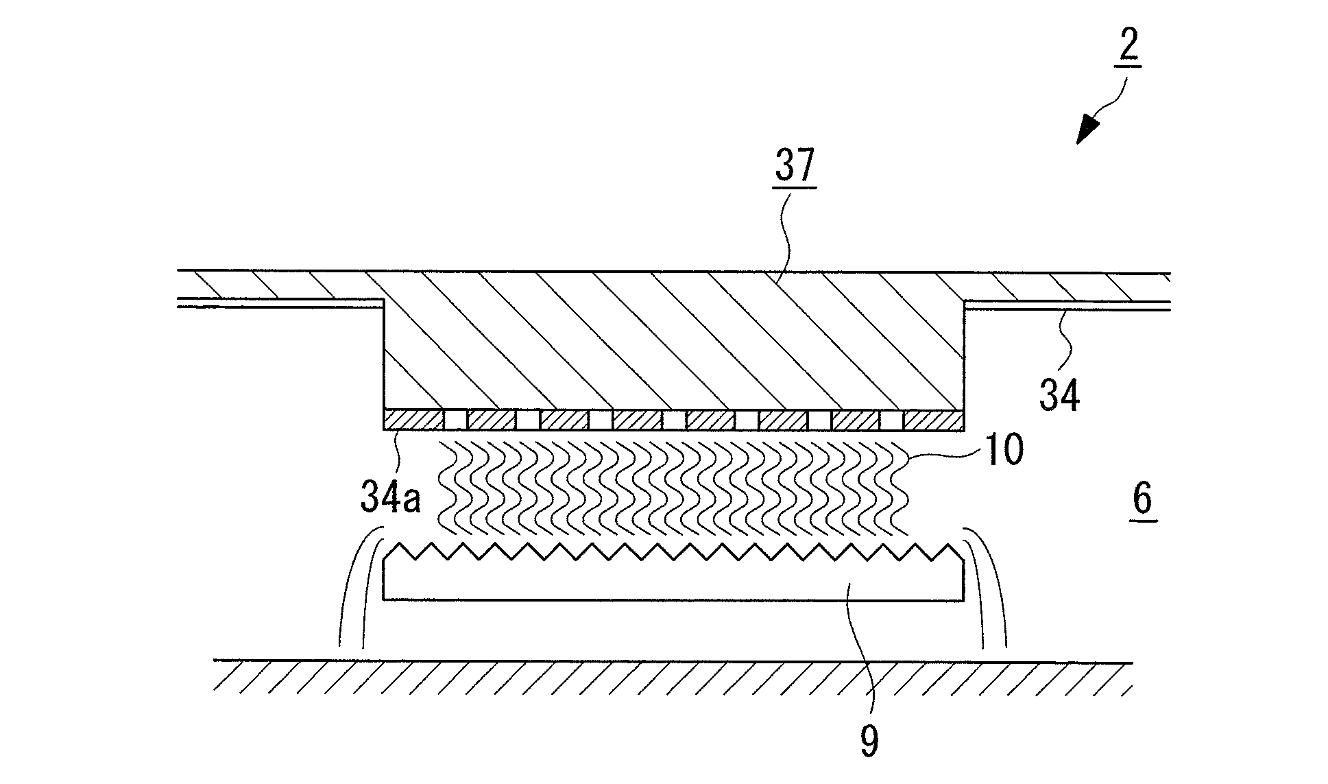
However, when the part 4a of the pressure bulkhead 4 is lowered toward the reheat chamber 6 in this way, the distance from the part 4a of the pressure bulkhead 4 having the holes 8 to the tray 9 is shortened, and the condensed water on the low-pressure side that flows down is mixed with the tray 9. There is a problem that the gas-liquid contact time of the steam on the high pressure side is shortened, and the reheating efficiency is lowered.
[0021] On the other hand, when the low-pressure side cooling tube group is placed above the condensed water reservoir without lowering part of the pressure bulkhead toward the reheat chamber, there is a problem that the overall size of the condenser increases.
Method used
Image
Click on the blue label to locate the original text in one second.
Reading with bidirectional positioning of images and text.
Examples
no. 1 approach
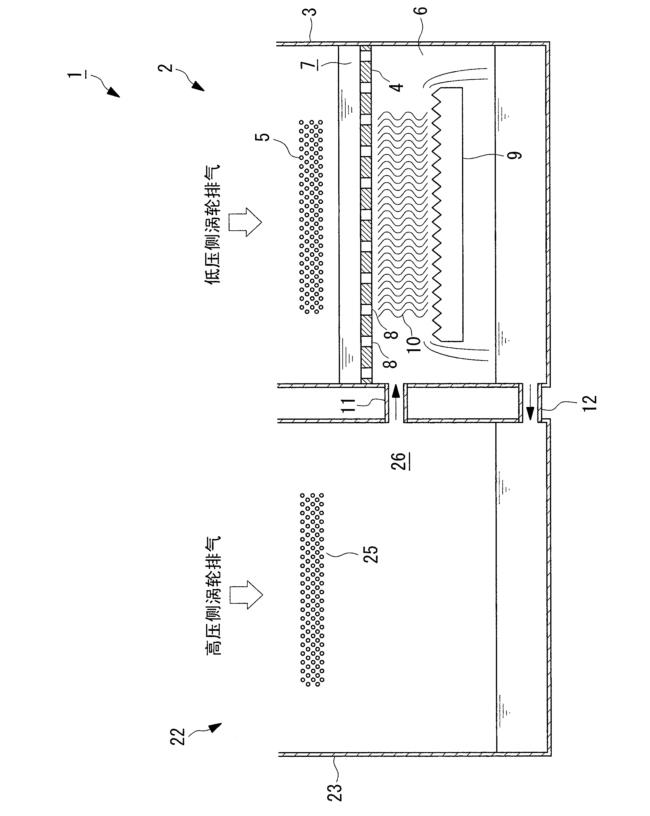
[0054] Below, according to figure 1 About the multi-stage pressure condenser involved in the present invention figure 1 Be explained.
[0055] figure 1 A schematic configuration diagram of the multistage pressure condenser according to this embodiment is shown in .
[0056] The steam turbine equipment (not shown) with the illustrated multi-stage pressure condenser 1 mainly includes: a steam turbine (not shown); a multi-stage pressure condenser 1; a boiler (not shown).
[0057] In the steam turbine plant, the steam expanded and worked by the steam turbine is introduced from the steam turbine into the multi-stage condenser 1, cooled in the multi-stage condenser 1, and condensed to form condensed water. The condensed water condensed in the multi-stage condenser 1 is heated by a feed water heater (not shown), and then supplied to the boiler. The condensed water supplied to the boiler is turned into steam and used as a driving source of the steam turbine.
[0058] Multi-sta...
no. 2 approach
[0088] The multistage pressure condenser of this embodiment and the steam turbine provided therewith are different from the first embodiment in that the distance between the corrugated plates is variable, and the others are the same. Therefore, the same symbols are assigned to the same structures, and descriptions thereof are omitted.
[0089] The distance between the plurality of corrugated plates (plate-shaped members) arranged in parallel to each other is provided so as to be adjustable. For example, by changing the distance between the corrugated plates from approximately 5 mm described in the first embodiment to approximately 2 mm, the thickness of the downflow liquid film of the low-pressure side condensate flowing down between the corrugated plates can be adjusted, and the The flow rate of condensate on the low-pressure side becomes slower.
[0090] Without changing the length of the extending direction between the corrugated plates (the direction in which the low-pres...
no. 3 approach
[0094] The multistage pressure condenser of this embodiment and the steam turbine provided therewith are different from the first embodiment in that the corrugated plates have grooves that open toward the low-pressure side condensate flowing down, and are otherwise the same. Therefore, the same symbols are assigned to the same structures, and descriptions thereof are omitted.
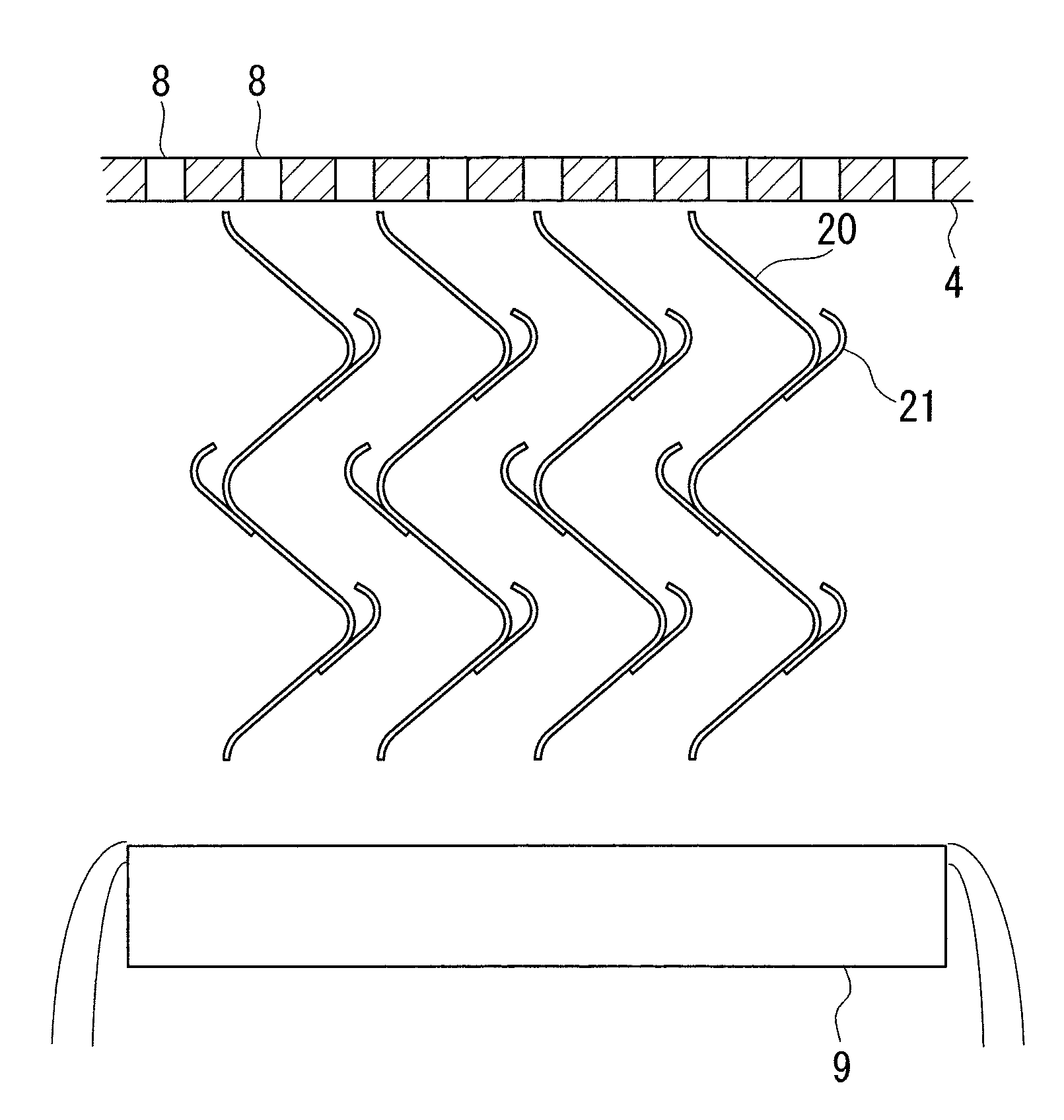
[0095] figure 2 A partial enlarged schematic configuration diagram of the low-pressure side condenser of the multi-stage pressure condenser according to the present embodiment is shown in .
[0096] The corrugated plate 20 presents a concavo-convex shape (zigzag shape) in which a plurality of (at least one) valleys are formed alternately in the cross-section of the condensed water on the low pressure side in the direction of flow down, and as figure 2 As shown, the concave-convex convex portion has a groove portion 21 that opens toward the low-pressure side condensate that flows down along the surfac...
PUM
Abstract
A multistage pressure condenser equipped with: a pressure bulkhead (4), which has multiple holes (8) and partitions a low-pressure-side low-pressure chamber (2) in the vertical direction; a cooling pipe group (5), which is provided in the upper part of the low-pressure chamber (2) partitioned by the pressure bulkhead (4), and which condenses low-pressure-side steam into low-pressure-side condensate by means of the exchange of heat between cooling water introduced into the pipe group and low-pressure-side steam introduced into the low-pressure chamber (2); a reheating chamber (6), which is the lower part of the low-pressure chamber (2) partitioned by the pressure bulkhead (4), and in which low-pressure-side condensate flowing down through the holes (8) in the pressure bulkhead (4) accumulates; a high-pressure-side steam introduction means (11) that introduces the high-pressure-side steam in a high-pressure-side high-pressure chamber (22) into the reheating chamber (6); and multiple plate-shaped members (10) arranged beneath the pressure bulkhead (4) parallel to each other in the direction in which the low-pressure-side condensate flows down from the holes (8) in the pressure bulkhead (4). The cross section of each plate-shaped member (10) in the direction of flow of the low-pressure-side condensate forms at least one concavo-convex shape.
Description
technical field [0001] The invention relates to a multi-stage pressure condenser for a steam turbineplant. Background technique [0002] Generally, in steam turbine equipment and the like, steam that drives the steam turbine is discharged from the turbine and guided to a condenser. The steam introduced into the condenser exchanges heat with the cooling water introduced into the condenser and is condensed to form condensed water. The condensed water condensed in the condenser is heated by the heater and supplied to the boiler. The heated condensed water supplied to the boiler is turned into steam and used as a driving source of the steam turbine. [0003] In such steam turbine equipment, since the temperature of the condensed water guided from the condenser to the heater is higher, the efficiency of the equipment is improved, or in order to suppress the amount of cooling water used when exchanging heat in the condenser, multi-stage pressure is adopted. condenser. [0004...
Claims
Application Information
Patent Timeline
Application Date:The date an application was filed.
Publication Date:The date a patent or application was officially published.
First Publication Date:The earliest publication date of a patent with the same application number.
Issue Date:Publication date of the patent grant document.
PCT Entry Date:The Entry date of PCT National Phase.
Estimated Expiry Date:The statutory expiry date of a patent right according to the Patent Law, and it is the longest term of protection that the patent right can achieve without the termination of the patent right due to other reasons(Term extension factor has been taken into account ).
Invalid Date:Actual expiry date is based on effective date or publication date of legal transaction data of invalid patent.
