Velocity gradient optimized type planet agitator

A planetary mixer and velocity gradient technology, which is applied in cement mixing devices, chemical instruments and methods, clay preparation devices, etc., can solve the problems of large velocity gradient and uneven distribution of velocity field of stirring blade motion, and achieve long service life, processing and manufacturing. And the effect of convenient disassembly and assembly, accurate transmission ratio

Inactive Publication Date: 2014-11-05
CHANGAN UNIV
View PDF5 Cites 0 Cited by
  • Summary
  • Abstract
  • Description
  • Claims
  • Application Information

AI Technical Summary

Problems solved by technology

[0005] The technical problem to be solved by the present invention is to provide a speed-gradient-optimized planetary mixer, which has a simple structure, reasonable design, easy operation and good use effect, and can effectively solve the problem of the existing vertical shaft planetary mixer. The mixer has problems such as uneven distribution of the velocity field of the mixing blade motion and large velocity gradient.

Method used


Image

  • Velocity gradient optimized type planet agitator
  • Velocity gradient optimized type planet agitator
  • Velocity gradient optimized type planet agitator

Examples


Embodiment 1

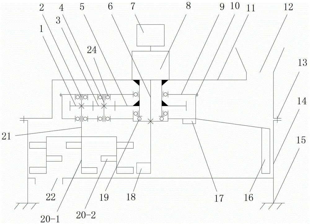
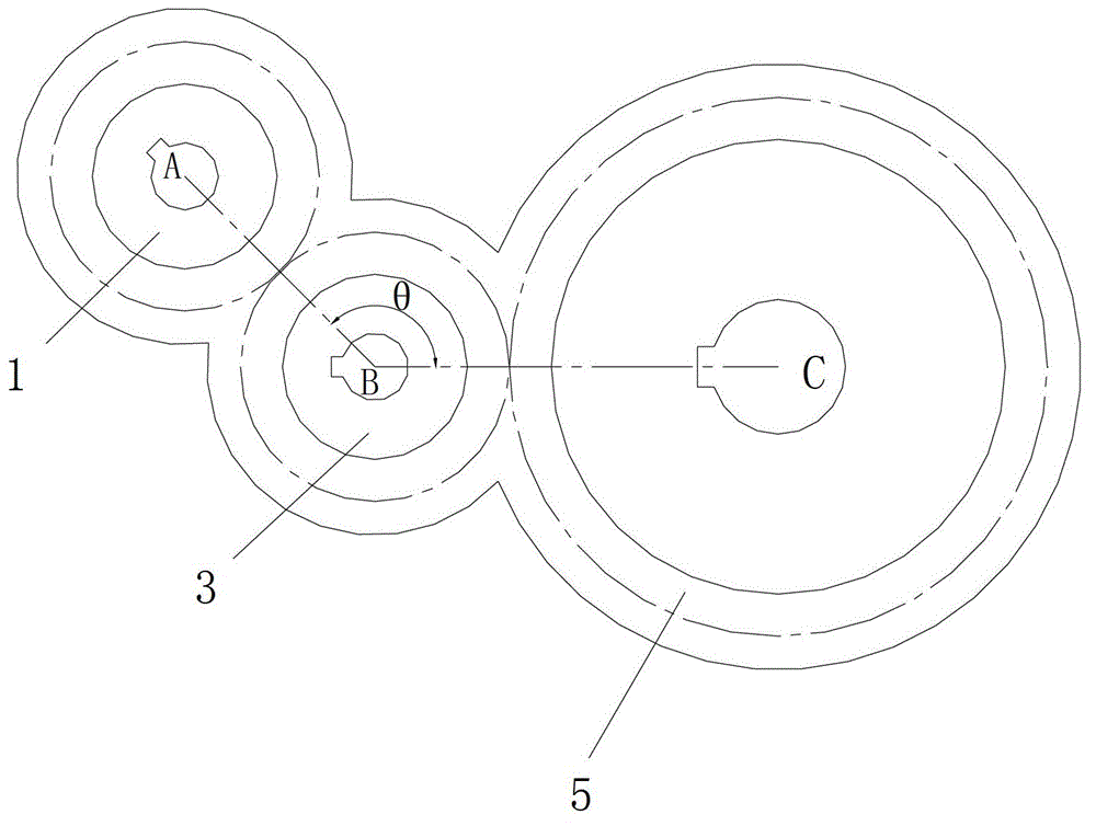
[0042] Such as figure 1 , figure 2 As shown, the present invention includes a casing, a transmission device and a stirring shaft 21 installed in the casing, the casing is arranged horizontally, and the stirring shaft 21 is arranged vertically and its number is one or more indivual. The transmission device includes a box body 9 driven by a drive mechanism to continuously rotate horizontally, a sun gear 5 and a transmission gear set installed in the box body 9, the box body 9 is connected with the drive mechanism, and the transmission gear set The number is the same as the number of the stirring shaft 21; the transmission gear set includes the first planetary gear 3 installed in the case 9 through the installation shaft 4 and the second planetary gear 1 coaxially sleeved on the stirring shaft 21, the The first planetary gear 3 , the second planetary gear 1 and the sun gear 5 are arranged on the same horizontal plane, the first planetary gear 3 meshes with the sun gear 5 , and...

Embodiment 2

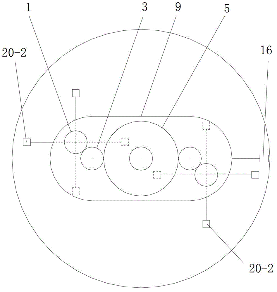
[0074] In this example, if image 3 As shown, the difference from Example 1 is that the number of the stirring shaft 21 and the transmission gear set is two, the shape of the box body 9 is a rounded rectangle, and the two stirring shafts 21 are respectively installed On the two transmission gear sets, and the two stirring shafts 21 and the two transmission gear sets are respectively symmetrically installed on the left and right sides of the power output shaft one 6, and the power output shaft one 6 is arranged on the box The middle part of body 9. During actual processing, the quantities of the stirring shaft 21 and the transmission gear sets can be adjusted respectively according to actual needs.

[0075] When the number of the stirring shaft 21 and the transmission gear set is multiple, the structure and size of the multiple transmission gear sets are the same, and the multiple stirring shafts 21 and the multiple transmission gear sets are all the same. Evenly arranged alo...

Embodiment 3

[0079] In this example, if Figure 4 As shown, the difference from Embodiment 2 is that the number of the stirring shaft 21 and the transmission gear set is three, and the three stirring shafts 21 and the three transmission gear sets are evenly arranged along the circumferential direction. , and the three agitating shafts 21 are installed on three of the plurality of transmission gear sets respectively.

[0080] In this embodiment, the structures, dimensions, connections and working principles of the remaining parts are the same as those in Embodiment 2.


PUM


Abstract

The invention discloses a velocity gradient optimized type planet agitator. The velocity gradient optimized type planet agitator comprises a machine shell, a driving device and agitator shafts, wherein the quantity of the agitator shafts is one or more than one; the driving device comprises a box body which is driven to rotate through the driving mechanism, as well as a sun wheel and driving gear groups arranged in the box body, and the quantity of the driving gear groups is as the same as that of the agitator shafts; each driving gear group comprises a first planet gear and a second planet gear which is coaxially sleeved on the corresponding agitator shaft; the first planet gear, the second planet gear and the sun wheel are arranged on the same horizontal plane and the center point of the second planet gear, the center point of the first planet gear and the center point of the sun wheel are non-collinear; and the first planet gear is meshed with the sun wheel, and the second planet gear is meshed with the first planet gear. The velocity gradient optimized type planet agitator provided by the invention has the advantages that the structure is simple, the design is reasonable, the use and operation are simple, the using effect is good, and the velocity gradient optimized type planet agitator solves problems that the existing upright shaft planet agitator has the problem that the distribution of an agitator blade kinematic velocity filed is not uniform, and the velocity gradient is large and the like.

Description

technical field [0001] The invention relates to a planetary mixer, in particular to a speed gradient optimized planetary mixer. Background technique [0002] In the mixing machinery of the mixture, the movement track of the mixing blades of the vertical shaft planetary mixing machines currently on the market is mostly a long epitrochoid. The gradient is large, and the distribution of stirring linear velocity and angular velocity is unreasonable, and even a static point (that is, the point where the stirring velocity is zero) will appear due to the superposition of rotation and revolution velocity. This is due to the unreasonable design of the mixer transmission mechanism, which causes the stirring speed of the stirring device to be very uneven and the speed gradient is large, that is, the stirring speed of some blades in the stirring device is too high and the stirring speed of the other part of the blades is too small. During the mixing process, the speed of the state chan...

Claims


Application Information

Patent Timeline
Patent Type & Authority Patents(China)
IPC IPC(8): B28C5/16
Inventor 赵悟田建涛朱霖龙潘旭磊任国涛刘小玲周纯冯忠绪
Owner CHANGAN UNIV
Why Eureka
Try Eureka